










The components inside a VFD control panel should be selected as a coordinated system. The drive is important, but it is not the entire panel: incoming power, isolation, protection, control signals, ventilation, enclosure construction and external interfaces all affect the finished arrangement. This guide explains the functional role of each component group, why the drive does not define the control system around it, and what to confirm before treating a component list as a design.
Exact part numbers, ratings, brands and certification status must be confirmed for the actual motor, drive and project.
Start with the panel function
Before listing components, define what the panel must do. Record the motor and supply data, the required speed control, operating modes, feedback signals, alarm requirements, local interface and installation environment. A component list without that context can create a panel that looks complete but does not meet the process requirement.
Main component groups
| Component group | Functional purpose | What must be confirmed |
|---|---|---|
| Incoming isolation and protection | Provides the project-defined means to isolate and protect the panel supply | Supply data, protective arrangement and applicable project requirements |
| Variable-frequency drive | Controls the motor according to the selected operating method | Motor data, duty, control range, feedback and manufacturer requirements |
| Motor-side connections | Connects the drive arrangement to the actual motor circuit | Cable, motor, installation and manufacturer requirements |
| Control interface | Receives commands, interlocks, feedback and alarms | I/O list, signal type, operating modes and responsibility boundaries |
| HMI or local controls | Displays status and allows approved local interaction | Operator needs, access and required information |
| Enclosure and thermal provisions | Houses and protects the equipment in the installation environment | Mounting, heat, access, cable entry and exact enclosure documentation |
| Communication interface | Connects to another system when required by the project | Protocol, network responsibility, cybersecurity and commissioning scope |
This is a functional map, not a universal bill of materials. The final component selection belongs to the approved design for the actual equipment.
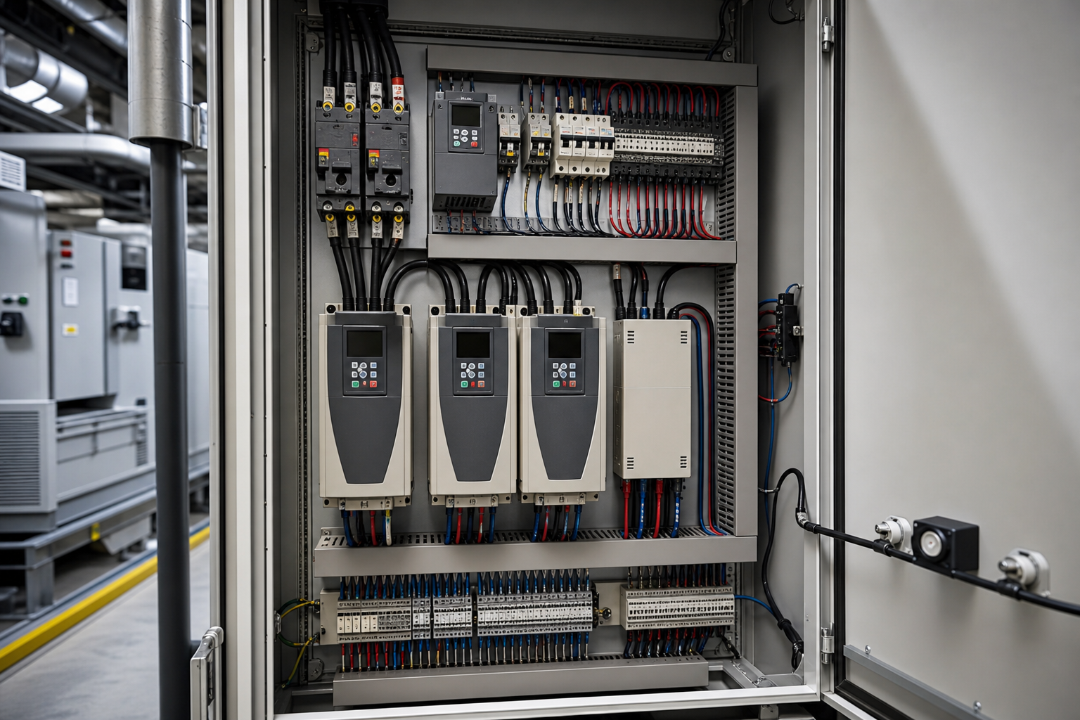
How the component groups interact
The groups fail or succeed together. A drive sized correctly for the motor still trips repeatedly if the incoming protection is mismatched to its input characteristics. A well-specified control interface still leaves operators blind if the HMI scope was cut from the order. The thermal group is the classic weak point: drives dissipate a meaningful share of their power as heat, and an enclosure sized by component footprint rather than by heat load cooks its electronics slowly. Review the power path, control signals, thermal conditions, access, wiring responsibility, and equipment documentation as one coordinated design.
The drive does not define the entire control system
A VFD may accept local commands, PLC commands, analog signals, digital signals or network instructions, depending on the application. The panel design should identify which control source is authoritative and how permissives, alarms and faults are handled.
The project should also define what happens when a sensor fails, a communication link is unavailable or a protective device operates. These are control and process decisions, not assumptions that can be copied from a generic drive panel image.

Consider enclosure and thermal requirements together
Drive equipment can influence the thermal conditions inside a cabinet. Review the selected model’s documentation, ambient conditions, mounting arrangement, cable entry and maintenance access. If ventilation or other thermal provisions are required, the final solution should be confirmed for the actual enclosure and installation.
Do not infer a NEMA/IP rating, cooling performance or certification from the presence of a fan, filter or similar accessory. Those are model- and configuration-specific claims. For the first thermal estimate, the enclosure temperature rise calculator converts the heat load and enclosure surface into an expected internal temperature.
Standards context for component selection
- UL 508A — the industrial control panel standard for the NEC market. It governs how components combine into a listed panel: wiring practice, spacings, overcurrent protection, and the marked short-circuit current rating established for the assembled whole rather than the individual parts.
- NFPA 79 — the industrial-machinery electrical standard in the NEC market, defining the machine-level environment the panel’s components serve: conductor protection, disconnecting means, and control-circuit expectations.
- IEC 61439 — the IEC assembly framework; the component coordination that UL 508A handles as a listing, this series handles through design verification of the assembly, with the installed devices identified in the assembly documents.
- NEMA 250 / IEC 60529 — the enclosure protection references behind NEMA types and IP codes for the cabinet that houses everything above.
Prepare a component review checklist
- What is the function of each power and control component?
- Which component ratings depend on the selected motor, drive, or supply?
- How are alarms, interlocks, feedback, and external interfaces represented?
- What documentation is required to verify the final arrangement?
Before requesting a quotation, provide the motor information, process objective, operating modes, control I/O, communication requirements, environment and documentation requirements. Ask the manufacturer to identify the component scope, interfaces and exclusions.
For related equipment, review the Frequency Converter Electrical Cabinet, PLC Control Cabinet and Electrical Control Panel Components.
Frequently asked questions
Is the VFD the only important component?
No. The drive is one part of a coordinated power, control, interface and enclosure arrangement. Most field failures trace to the surrounding components or their coordination, not to the drive itself.
Does every VFD panel use the same protection and control components?
No. The components depend on the actual supply, motor, drive model, operating method, environment and project requirements. Two panels with the same drive rating can differ in every other group.
Follow-up: which component is most often under-specified?
The thermal arrangement. Panels are routinely ordered by footprint and device count, leaving the heat load uncalculated until the first hot season. A thermal check at order time — heat load, ambient, enclosure surface — is the cheapest reliability improvement available.
Do VFD panels need input and output reactors or filters?
Sometimes — long motor cables, harmonic limits, or sensitive equipment sharing the supply push the answer toward them, per the drive manufacturer’s application guidance and the project’s power-quality requirements. They are application decisions, not universal fitments.
Who supplies the drive parameter set?
The commissioning scope should say so. The panel builder typically delivers the hardware with terminals ready; the machine or process engineer supplies the parameters and sequence. Confirming this split at order time prevents a panel that works electrically but has never been told what to do.
Can this article replace a panel schematic?
No. A schematic and component schedule must be developed and reviewed for the actual installation.
Ordering scenarios
An OEM building pump or fan skids typically orders its first VFD panel as a single pilot unit with the full component schedule and thermal documentation, proves it on the test bench with the production motor, then releases series panels against the frozen schedule. The binding constraints are the drive delivery time and the parameter-handover date, because both arrive later than the panel and both gate shipment of the skid.
A system integrator serving both NEC- and IEC-market clients should decide the component regime per destination on the first order: the North American panel is assembled and documented under UL 508A with NFPA 79-aligned machine documentation, while the IEC-market panel carries IEC 61439 assembly verification. Sharing one component list across both markets without that split produces a panel whose evidence package matches neither destination cleanly.
Use the control panel components guide for terminology and confirm the actual bill of materials only after the project inputs are complete.
 EN
EN