







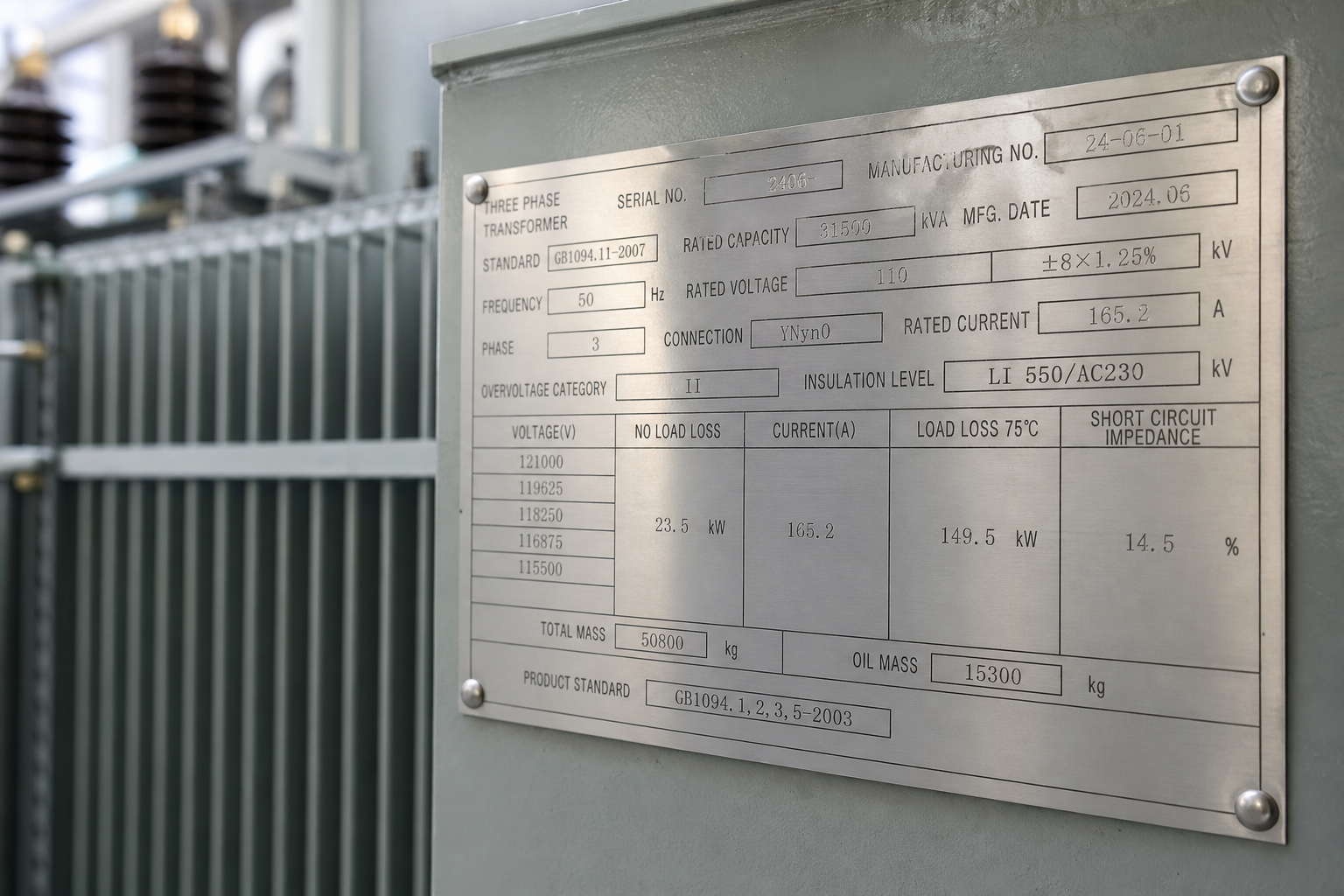
The transformer nameplate is the contract between manufacturer, standards, and your installation — every commissioning check, protection setting, and maintenance decision refers back to it. Yet it is routinely photographed once and filed. This guide walks through each field on a typical distribution transformer nameplate (pole-mounted, pad-mounted, or dry-type), what it means, and which fields you will actually use.
Standards require the nameplate to carry this information: IEC 60076-1 specifies the minimum data for IEC-built units, and IEEE C57.12.00 does the same for the North American route. Field wording varies between regimes; the content below is what you will find on almost any modern unit.
The identity block
- Manufacturer, serial number, year of manufacture. The serial is your reference for every future document — test reports, spare parts, warranty. Photograph it at receipt.
- Standards designation. “IEC 60076” or “IEEE C57.12.00” — tells you which design and test regime the unit was verified against, which matters when you interpret test values.
- Type / model designation. The manufacturer’s design family; keep it in your asset register because replacement coils and drawings key off it.
The rating block
- Rated power (kVA). The continuous rating at reference conditions (reference ambient and cooling mode). Two cautions: it assumes the stated cooling (ONAN vs ONAF/AF — see our cooling class guide), and it assumes reference environmental conditions — altitude above 2,000 m and high ambient derate it.
- Rated voltages (primary and secondary). For units with taps: the principal tap voltage plus the tapping range (e.g., ±2×2.5%). The ratio implied here is what your metering and protection assume.
- Rated current. Sometimes stated, always derivable: I = kVA × 1,000 ÷ (√3 × V) three-phase (see our kVA-to-amps guide).
- Rated frequency and phases. 50/60 Hz units are not interchangeable without design review.
- Vector group (e.g., Dyn11) or winding connection. The winding connection and phase displacement — our vector group guide covers why this constrains grounding, paralleling, and protection.
- Impedance voltage (%). The short-circuit impedance on rating — the number that sets your secondary fault level and voltage regulation. Protection engineers use it on day one; it belongs in every fault study.
- Insulation levels: power-frequency and impulse (BIL). E.g., a 15 kV-class unit commonly carries 34/95 kV (power-frequency / BIL) ratings. This pair defines dielectric capability — verify it matches your exposure before energization, not after.
The construction and thermal block
- Cooling class. ONAN/ONAF (oil), AN/AF (dry) — the fans question: an ONAF/AF rating is only available with working fans.
- Insulation system class and temperature rise. Dry-type: e.g., Class F (155 °C) with 100 K rise or Class H with 80 K rise — the class/ rise combination is the real thermal statement (see our dry-type types guide). Oil units: average winding temperature rise (commonly 65 K) plus top-oil rise, and the oil temperature class.
- Fluid type and volume (oil units). Mineral oil, natural or synthetic ester — with total mass and fluid mass. This field decides your containment, fire, and environmental obligations.
- Masses. Total, and sometimes fluid and core-coil separately — lift planning data, not trivia.
The protection and compliance block
- Tap positions. Off-circuit tap changer or link board positions and voltages — record which tap the unit shipped on (the commissioning setting).
- Serial-anchored documents referenced: routine test report number, sometimes a type-test reference. If the nameplate carries a standard’s mark (CE) or efficiency designation (DOE-compliant), the supporting documentation should exist in the handover pack.
- Sound level (dB(A)). Sometimes stated; contractual where noise-sensitive.
- Oil volume, preservation type (conservator / hermetically sealed), and gauge provisions — the maintenance planning inputs.
Field-by-field: what commissioning actually uses
| Field | First real use |
|---|---|
| Ratio + vector group | Phasing and metering checks before closing the breaker |
| Impedance | Fault study validation; breaker and relay settings |
| BIL | Confirming insulation coordination for the exposure |
| Tap shipped position | Setting expectation for measured secondary voltage |
| Temperature rise class | Interpreting measured temperatures as normal vs abnormal |
| Fluid type/volume | Containment, fire code, first oil sample interpretation |
| Masses | Lift plan at installation and at replacement |
The nameplate is also a procurement instrument. On a 50-unit order with a fixed budget, the fields above become the acceptance checklist that keeps the budget honest: the serial-anchored routine test report must show measured values matching the nameplate’s commitments (ratio, impedance, losses within tolerance), and the type-test reference — where the nameplate carries one — should be a report number a third party can confirm with the issuing lab rather than a family claim. Spending verification effort where it pays means prioritizing the loss values and withstand evidence (the fields where fabrication circulates) over cosmetic data, and photographing every plate at receipt so the fleet’s paperwork starts aligned with the metal. Fifty disciplined receiving inspections cost a fraction of one warranty dispute conducted without evidence.
FAQ
The nameplate says ONAN but the datasheet quotes higher kVA — which is right?
Both, if the unit is ONAN/ONAF: the lower figure is natural-cooled, the higher with fans running. Fans add a failure mode and a noise step — size on the natural rating for continuous duty and treat fan-assisted capacity as overload headroom.
My measured secondary voltage differs from the nameplate ratio — is the transformer faulty?
Usually it is regulation (load-dependent voltage drop across impedance) or tap position, not a winding fault. Check the shipped tap against measured primary before suspecting the ratio; ratio errors are a routine-test item and rare on a healthy unit.
Are nameplate values guaranteed or typical?
Rated values (kVA, voltages, impedance) are contractual; measured quantities (losses, impedance as tested, sound) carry standard tolerances — guaranteed loss values and tolerances belong in the purchase contract and the routine test report shows what was actually measured on your serial number.
How do I bind the guaranteed values into the purchase contract?
Name the guaranteed figures (losses, impedance, rise) with their tolerances as contract lines, require the routine test report per serial number to show measured values against them, and make acceptance conditional on the comparison. The nameplate then restates what the contract already enforces.
On a 50-unit order with a fixed budget, which fields justify third-party verification?
The ones where nonconformance hides: measured losses versus guaranteed values, withstand test results, and any type-test reference the quotation leans on. Confirming a type-test report number with the issuing lab is cheap; a fixture inspection at FAT covering those fields closes the loop on the rest.
Where do I find the serial number on older units?
On the main nameplate plate, typically tank-mounted on pole and pad units or enclosure-mounted on dry-type. Faded plates can often be recovered from utility records or the manufacturer’s build records using photographs of adjacent fields.
Related reading
- pole-mounted transformers — the overhead format whose nameplates this guide’s readers handle.
- distribution transformers — the product family behind these nameplate fields.
- kVA calculator — turn nameplate kVA and voltage into operating currents.
Engineering note: this article is a nameplate-reading reference from ElectricalCabinet.net, a manufacturer of distribution transformers (pole-mounted, pad-mounted, dry-type) and packaged substations. Nameplate interpretation supports — but never replaces — commissioning testing by qualified personnel under the applicable codes.
 EN