










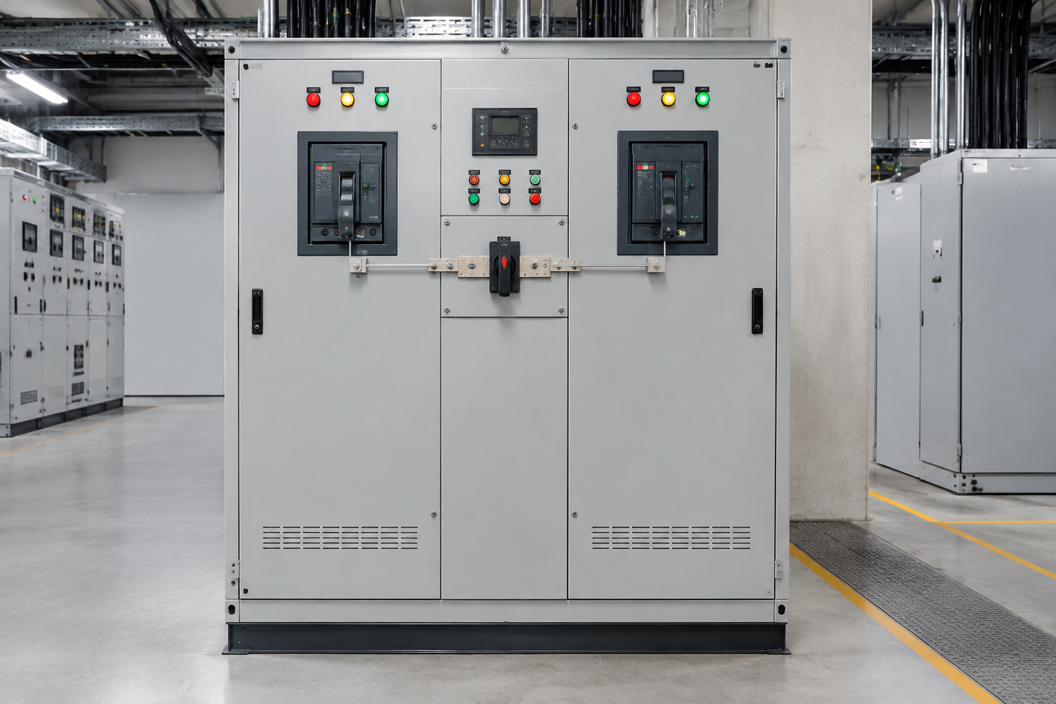
An automatic transfer switch (ATS) moves a load between two power sources — normally utility and generator — without an operator: it senses source failure and restoration, starts the backup source if required, transfers the load with the correct delays and sequencing, and returns it when the preferred source is stable. Defining its application scope for backup power means deciding source availability logic, load priorities, transfer sequence, control interfaces, cabinet integration, and the commissioning checks that prove all of it under real failure conditions. This guide covers those decisions with the comparison tables and standards context that keep an ATS project coordinated. It is for design and procurement discussions; final installation, code, safety, testing, and qualified engineering requirements must be confirmed for the project.
In specification language the device is simply a transfer switch, and because backup schemes almost always pair a generator and transfer switch, the two are specified together: you will see generator transfer switch on nameplates, a transfer switch for generator duty in catalogs, and generators with automatic transfer switches sold as one reviewed package — the switch’s start interface, sensing windows, and ratings must match the specific generators and transfer switches they supervise. The first fork in selection is manual versus automatic: a manual transfer switch relies on an operator to execute the changeover, while the automatic transfer switch this guide describes runs the sequence unattended.
Start with the process and boundary
Document the process steps, equipment, field signals, power sources, operating modes, environment, and the responsibilities of the controls integrator, cabinet builder, installer, and operator. For ATS projects the load boundary is the first decision: the whole installation on one large switch, or critical loads separated onto a dedicated transfer scheme with non-critical loads shed during outage operation.
Transfer topologies: the open versus closed decision
| Attribute | Open transition (break-before-make) | Closed transition (make-before-break, momentary paralleling) |
|---|---|---|
| Switching behavior | Load momentarily disconnected during transfer | Sources paralleled briefly, then the outgoing source opens |
| Load impact | A brief interruption — motors and drives see a power gap | No interruption; requires both sources synchronized |
| Generator and switch complexity | Simpler logic and construction | Requires synchronizing, protection during parallel, and rated for the duty |
| Typical use | Standard backup for loads tolerating seconds of transfer | Processes where even momentary loss is unacceptable; also soft-load variants |
| Standard-market note | The default ATS product class in most markets | A specialized class with additional engineering and utility approval implications |
Below both sit delayed-transfer and bypass-isolation variants, and above them sit static transfer switches for sub-cycle transfers of electronic loads — the application’s tolerance for the transfer gap is the selection variable that decides the class.
The transfer sequence, timing by timing
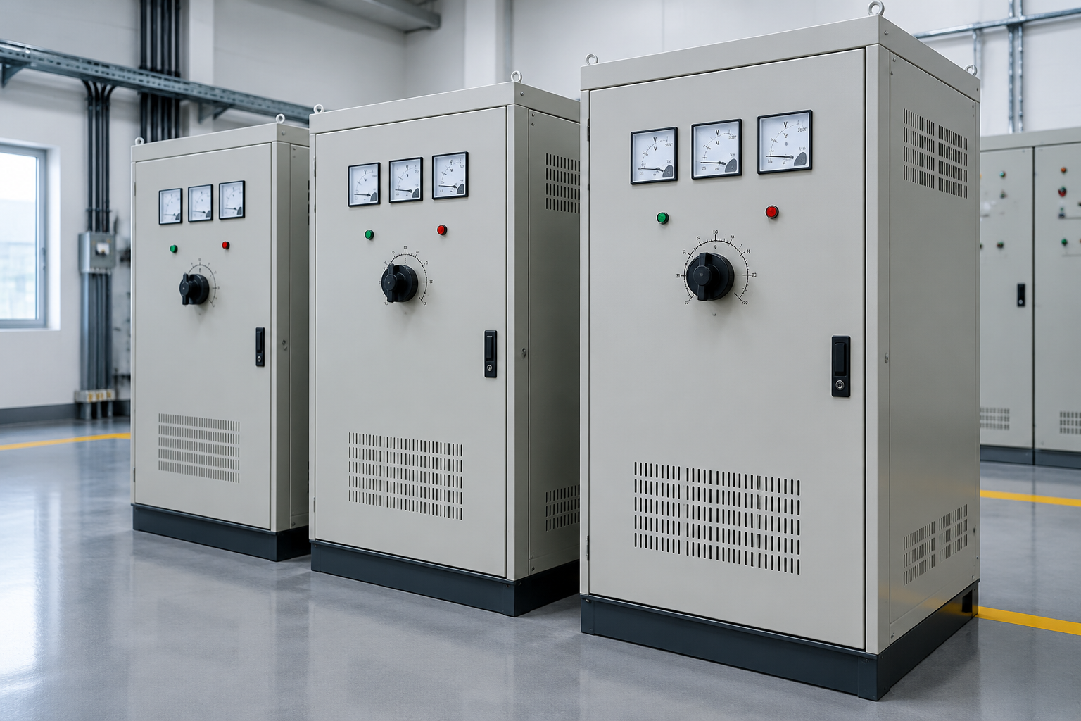
A standard utility-to-generator sequence runs: source failure sensed (with a ride-through delay to ignore transient dips) — start signal to the generator — generator ready (voltage and frequency within acceptance windows) — transfer executed — load picked up, with staggered re-connection of large loads so the generator is not hit with full starting current at once. Return runs the mirror image: utility stable for an agreed period (avoiding re-transfer onto a flaky source), then transfer back, then generator cooldown and stop. Every one of those delays is adjustable and every default is a design decision — the settings sheet is an engineering deliverable that belongs in the handover file, not inside the switch where nobody records it.
Load priority and shedding during outage operation
Generator capacity is finite, so backup operation is a load-management design: which feeders transfer at all, in what order they reconnect, and which are shed automatically or by operator choice. Motors need special handling — staggered restarts and, for large units, restart inhibition during initial pickup; the generator’s transient behavior under motor starting current sets the practical sequence. Where the ATS scheme integrates with a building management or PLC system, the load priority table becomes an interface document shared between the electrical and controls packages.
Cabinet and interface inputs
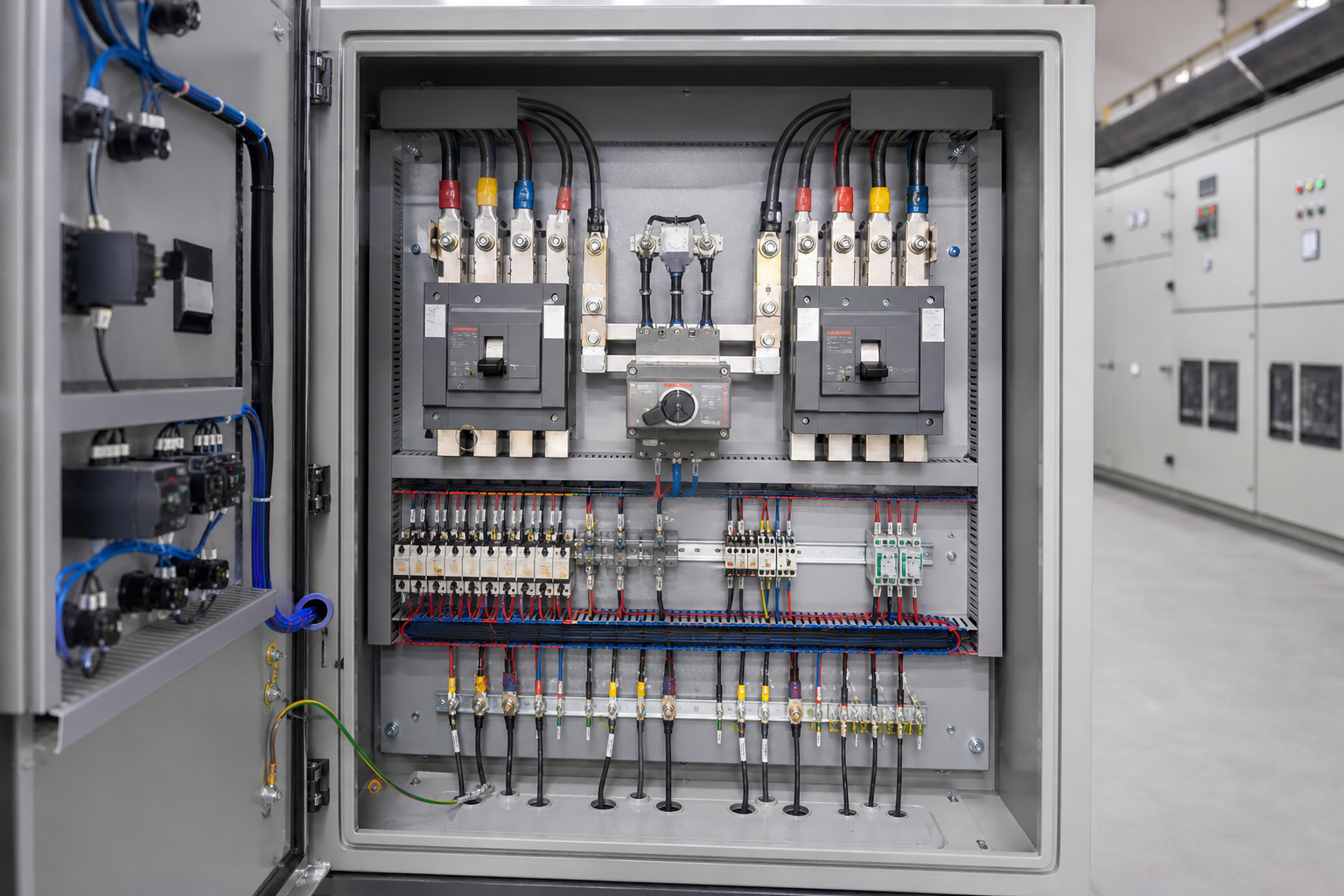
| Input | What to document |
|---|---|
| Equipment and signals | I/O list, ratings, sensors, actuators, terminals, network ports, and required isolation. |
| Environment and installation | Indoor or outdoor location, temperature, moisture, dust, access, mounting, cable entry, and service clearance. |
| Control sequence | Modes, permissives, alarms, interlocks, transfer or inspection decisions, and operator actions. |
| Evidence and handover | Drawings, labels, test records, parameter files, software backups, training, and maintenance instructions. |
Selection and review checklist
- Separate confirmed project data from assumptions and vendor options.
- Check interfaces between the field equipment, controller, HMI, network, and cabinet.
- Record open decisions, acceptance tests, and the person responsible for each item.
Do not copy a competitor’s performance, safety, cybersecurity, certification, or availability claim without project-specific evidence.
Standards and ratings for transfer equipment
Transfer switching equipment certifies under dedicated standards: IEC 60947-6-1 covers transfer switching equipment in IEC markets, and UL 1008 governs automatic transfer switches in North American listings, both defining construction, endurance, overload, and fault-withstand requirements — with the installation following the local wiring code (NEC provisions for transfer equipment and standby systems in North America; IEC 60364 contexts elsewhere). Ratings to verify on every quotation: the continuous current, the fault-withstand or short-circuit rating of the switch in its enclosure (with or without integral protection), the generator-start interface compatibility, and the endurance class against the expected transfer frequency. Where closed transition is involved, the momentary paralleling time limit and the protections active during it are engineering questions your utility may also care about — involve them early.
Commissioning: proving failure behavior on purpose
An untested ATS is a belief system, not backup power. Commissioning must exercise the real conditions: utility failure simulation (open the right breaker, not just press a test button), full transfer with representative load, motor restart behavior, return transfer, and generator cooldown cycle — with all timings recorded against the settings sheet. Then the documentation handover: settings record, sequence-of-operation description, test results, and operator training on manual operation, because the day the automatic system needs help will not be a convenient day.
Frequently asked questions
How fast does an ATS transfer?
The switch itself operates in fractions of a second to seconds depending on class and mechanism; total outage time on generator schemes is dominated by engine start and acceptance — commonly seconds to tens of seconds. Sub-cycle continuity is static-switch territory.
Can one ATS feed the whole facility?
Electrically often yes, operationally usually suboptimal — transferring only critical loads with a smaller scheme cuts generator size, transfer ratings, and testing disruption. The load-priority study usually pays for itself immediately.
What maintenance does an ATS need?
A scheduled program of contact inspection, mechanism exercise, transfer testing under controlled conditions, and settings verification. An ATS that has never transferred in years is a risk quietly compounding.
Do I need a bypass-isolation arrangement?
Where continuity during ATS maintenance matters — hospitals, data and process plants — bypass-isolation lets the switch be serviced without dropping the load. It adds cost and cabinet space; whether it is required is a risk decision, not a product default.
How do ATS settings interact with the utility supply?
Undervoltage sensing thresholds and ride-through delays decide whether the plant rides through a dip or transfers; settings too tight produce nuisance transfers, too loose produce equipment damage during sustained low voltage. The follow-up worth scheduling: review the transfer log against utility disturbance records after the first year, and tune — the measured reality of your feeder is the only valid basis for those thresholds.
Where does the ATS sit relative to the switchgear?
Typically on the main feeder between utility incomer, generator incomer, and the load distribution — often as part of or adjacent to the main LV switchboard; our medium voltage switchgear page covers the upstream lineup context.
Procurement scenarios
For a facility buying its first generator-ATS scheme, order the ATS with witnessed functional tests including a simulated utility failure under representative load, and insist on the settings sheet and sequence description as contract deliverables — the test report is the birth certificate of the backup system. For retrofit into a live switchboard, plan a bypass or temporary feed strategy for the installation window and order the ATS pre-configured with your settings so site time is mechanical, not engineering. For multi-site standardization, qualify one ATS model and settings template per site type, and order against that qualification — repeat orders referencing witnessed baseline tests keep both price negotiation and delivery to routine levels.
ElectricalCabinet.net integrates transfer schemes into complete power assemblies — see our stabilizers, regulators, and transformers comparison for the neighboring power-conditioning decisions, and the low voltage switchgear guide for the boards these switches live in.
 EN
EN