










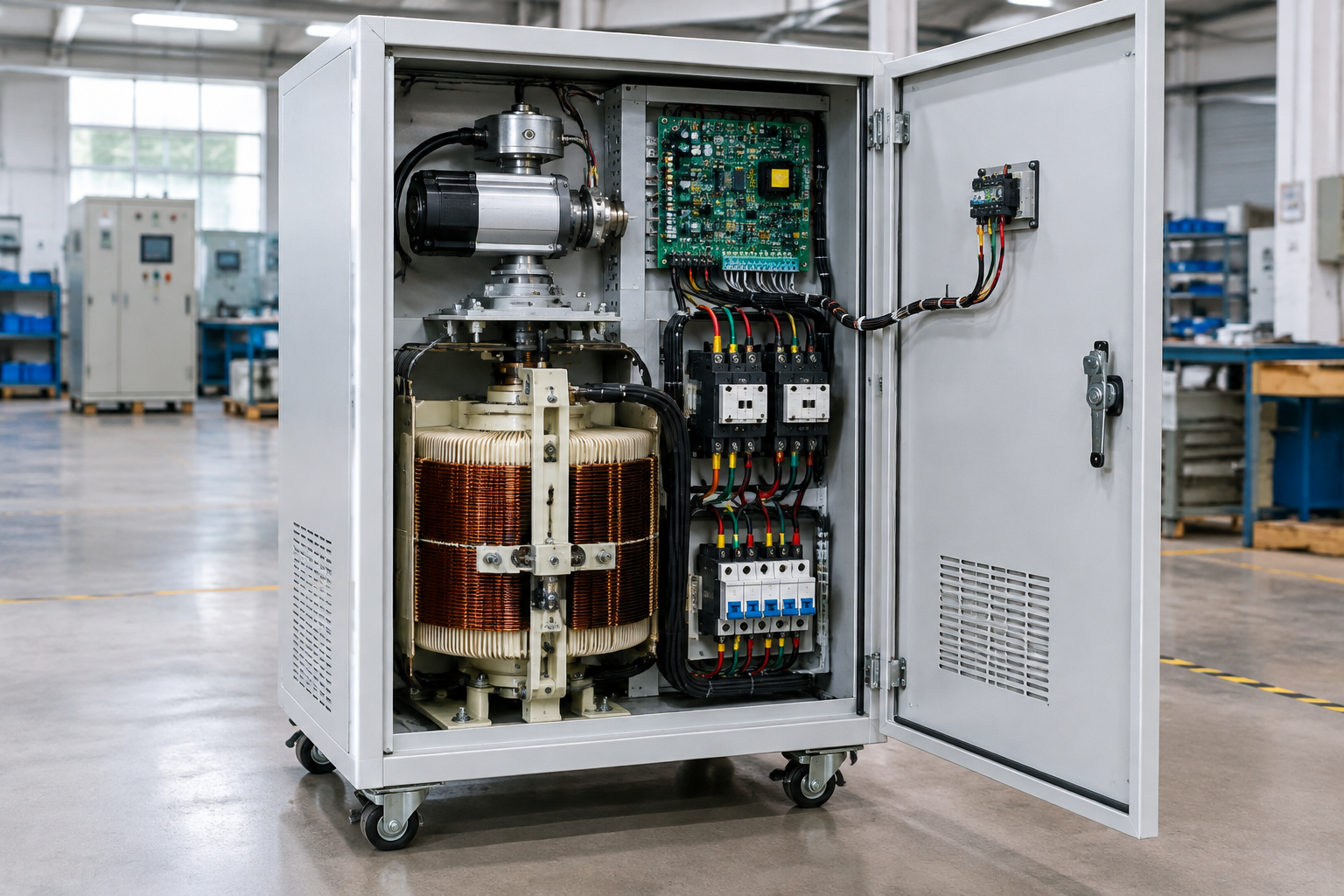
Stabilizers, regulators, and transformers solve three different supply problems, and choosing among them starts from a simple question: what is the actual disturbance? A transformer changes voltage level — permanently, by turns ratio, with no correction. A regulator holds voltage within a band by continuous or stepped adjustment of the ratio. A stabilizer — the industrial term for a fast, closed-loop corrective assembly built around a series transformer and a correction element — restores a wandering supply to a tight band automatically. Selecting the wrong device for the disturbance is the classic procurement error: a transformer cannot fix an unstable supply, and a stabilizer cannot correct a wrong system voltage by itself. This guide compares the three by electrical function, load, installation, enclosure, protection, and maintenance, and maps the decision path. Final electrical ratings, protection, installation, testing, and qualified engineering requirements must be confirmed for the actual project.
The functional comparison
| Attribute | Transformer | Voltage regulator | Automatic voltage stabilizer |
|---|---|---|---|
| Primary function | Change voltage level (and isolate) by fixed ratio | Maintain output within a band under varying input or load | Closed-loop correction of an unstable supply to a tight output band |
| Correction behavior | None — fixed ratio | Continuous or stepped ratio adjustment | Sense-compare-correct loop; speed set by technology (motorized variac, relay taps, or electronic stage) |
| Solves | Wrong system voltage, isolation needs, phase conversion arrangements | Slow drift on long feeders, distributed voltage regulation | Plant or equipment supply that wanders outside equipment tolerance |
| Does not solve | Voltage instability, sags, swells | Fast disturbances beyond its band and speed | Frequency deviation, harmonics, outages, deep sags below its range |
| Typical protection context | Overcurrent, differential, temperature | Overcurrent, over/under-voltage limits | Cut-outs, overload and short-circuit protection, bypass provisions |
| Maintenance profile | Insulation and cooling care; minimal moving parts | Mechanism wear depends on tap duty | Correction element service (brushes, relays, or power stage) on a schedule |
| Typical placement | Any level change point: MV/LV, isolation, distribution | Utility distribution, dedicated feeder ends | At the load or plant intake, downstream of the supply |
Decision path: from disturbance to device
First measure: log voltage at the point of common coupling and at the load over representative periods. If voltage is stable but at the wrong level, the answer is a transformer. If voltage drifts slowly with load or time of day within a moderate band, regulation — or a stabilizer sized for the plant — is the candidate. If voltage wanders widely or rapidly, a stabilizer with the measured range and appropriate correction speed is indicated; verify the largest motor’s starting behavior against the stabilizer’s overload capability before sizing. If the disturbance is outages or sub-cycle sags, none of these three is the answer — that territory belongs to UPS and ride-through systems, and saying so plainly saves projects from buying the wrong metal box for a power-quality problem.
Define the equipment and site boundary
Record source and load conditions, operating modes, environment, mounting, cable routes, access, maintenance ownership, and interfaces between the equipment, cabinet, installer, and operator.
Inputs to document
| Input | Why it matters |
|---|---|
| Electrical duty | Voltage, current, frequency, fault level, load type, switching or regulation duty, and protection assumptions. |
| Site and enclosure | Indoor or outdoor exposure, moisture, dust, corrosion, temperature, clearances, cooling, cable entry, and service space. |
| Controls and operation | Modes, alarms, bypass or isolation, interlocks, local interfaces, remote signals, labels, and operator sequence. |
| Verification and handover | Drawings, nameplate data, inspection points, test records, settings, manuals, spares, and maintenance instructions. |
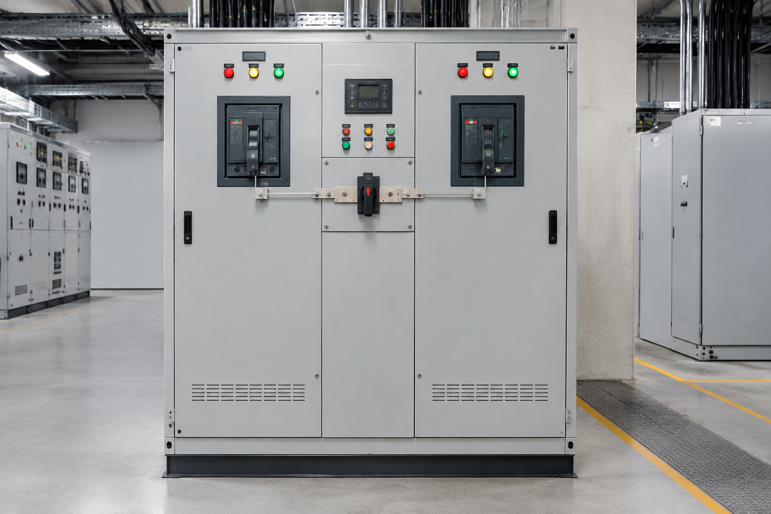
Review before release
- Separate confirmed project data from assumptions and vendor options.
- Check the boundary between equipment, enclosure, protection, cabling, and site installation.
- Record open decisions and acceptance evidence before procurement or fabrication.
Do not copy competitor certification, protection, performance, or availability claims without project-specific evidence.
Combinations and boundaries between the three
Real installations combine the devices, and the combinations are where scope discipline pays. A plant intake: transformer steps MV to LV, then a stabilizer conditions the LV supply for sensitive lines — the transformer cannot be omitted for wrong-level systems, and the stabilizer cannot replace it. A dedicated machine feed: an isolation transformer for clean separation plus a small stabilizer for the control supply. Distribution networks: regulators on long feeders doing the coarse work, equipment-level stabilization doing the fine work at the load. When specifying combinations, document which device owns which disturbance band — the measurement record is the contract between them.
Standards and verification across the three families
Transformers certify under the IEC 60076 series (oil and dry) or the IEEE C57 family, by power class. Regulators and stabilizers assemble transformer technology with switching and control into power assemblies: the assembly-level conversation follows IEC 61439-1/-2 in IEC markets, with correction electronics additionally meeting EMC requirements under the IEC 61000 series, and North American installations following the UL framework with NEC installation rules. At acceptance, require routine test records per unit — for stabilizers explicitly including regulation verification across the stated input range at agreed load points, and protection function checks; for transformers, the standard routine set including ratio and dielectric tests. Nameplate data must match the ordered specification, and where a device claims a correction range, the test record is the evidence that the range was actually verified.
Frequently asked questions
Is a stabilizer just a regulator with a different name?
In utility vocabulary the terms overlap; in industrial procurement they point at different products — regulators being ratio-adjusting devices for slow drift, stabilizers being closed-loop corrective assemblies at the load. Define by measured disturbance and required band, not by the label on the box.
Can a transformer improve voltage stability as a side effect?
Only incidentally — through impedance and load interaction. A transformer is not a correction device; if the measured problem is instability, order the correction device.
Do I need a stabilizer if I already have a regulator on the feeder?
Depends on the residual band at the load: if the regulated feeder still wanders outside equipment tolerance, equipment-level stabilization is justified. Measure at the load — the decision boundary is the equipment’s tolerance, not the utility’s statistics.
What does a stabilizer not protect against?
Outages, frequency deviation, harmonics beyond design, and deep sags below its correction range. Those need ride-through or conditioning technologies outside this comparison.
Which device owns power factor questions?
None of them — power factor correction is capacitor territory, interacting with but separate from all three. The follow-up worth an engineer’s hour: verify harmonic resonance between any capacitor bank and transformer impedance before installing both, because that interaction is the classic hidden failure in combined installations.
How do the maintenance demands compare?
Transformers ask the least; regulators wear with tap duty; stabilizers need scheduled service of their correction element. Budget the maintenance difference in the selection, not after the first fault.
Procurement scenarios
For a plant uncertain which device it needs, buy the measurement first — a power-quality logging survey at the intake and at the worst-affected load — and order the device the data names; the survey costs a fraction of any of the three boxes it prevents mis-buying. For a measured wide-swing supply feeding mixed motor and electronic loads, order the stabilizer with a witnessed regulation test and one spare correction-element set, and pair it with the transformer step already in the plan rather than asking either device to do both jobs. For multi-site rollouts of the same load profile, qualify one stabilizer design with a first-article test record and order repeats against it — repeat orders referencing witnessed baseline data compress delivery and price negotiation to routine levels.
If the boundary study points to a transformer rather than a stabilizer, our pad mounted transformer page lists the ratings and configurations we manufacture — and the stabilizer components anatomy and selection guide cover the stabilizer path in depth.
 EN
EN