










Low-voltage switchgear is a crucial component of electrical systems, providing both safety and control. Understanding the fundamentals is critical for anyone working in electrical engineering or maintenance.
This guide is intended to provide newcomers with an overview of the essential ideas, components, functions, and applications of low-voltage switchgear, laying the groundwork for further learning.
What is low-voltage switchgear?
A low-voltage switchgear (LV) is a three-phase power distribution unit that can supply electric power at up to 1,000 volts and current at up to 6,000 amps. Often used indoors, these are enclosed in a metal case containing copper conductors and a combination of circuit breakers and isolators.
In everyday project language the abbreviations dominate: an LV switchgear panel (or LV switchgear panels across a switchroom) is the same equipment, its outgoing devices are LV breakers, and electricians often refer to the lineup simply as electrical LV gear. The low voltage components inside—breakers, busbars, current transformers, relays, and the metering and control devices—are covered in the sections below, and the complete switchgear assembly is documented on a single-line switchgear schematic showing how each breaker connects to the bus.
Electrical Switchgear Types
There are three different classes of switchgear systems: low-voltage, medium-voltage, and high-voltage.
- High Voltage Switchgears: High-voltage switchgears (HV) are those that control 75KV of power or more. Because these breakers are designed for high-voltage use, they often include improved safety features.
- Medium Voltage Switchgear: Medium-voltage switchgear(MV) is utilized in systems ranging from 1 KV to 75 KV. This switchgear is commonly found in systems that include motors, feeder circuits, generators, and transmission and distribution lines.
- Low Voltage Switchgear: Low-voltage switchgear(LV) is designed to regulate systems up to 1KV. These are often found on the low-voltage sides of power distribution transformers and are employed in a wide range of industries.

Main Components of Low Voltage Switchgear
Low voltage switches, earth leakage circuit breakers, HRC fuses, electrical isolators, air circuit breakers (ACB), moulded case circuit breakers (MCCB), and tiny circuit breakers (MCB) are examples of low voltage switchgear with a 1KV rating.

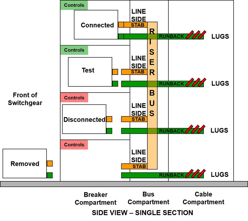
- Breaker compartment: Devices that automatically cut off electrical flow in the case of an overload or short circuit. Types include tiny circuit breakers (MCBs) and molded case circuit breakers (MCCBs).
- Switches: Mechanical devices for opening and closing electrical circuits. They can be operated manually or automatically.
- Bus compartment: The bus compartment is located behind the circuit breaker compartment and is likewise separated from it by solid barriers.
- HRC fuses: When the current surpasses a certain threshold, safety devices melt and break the circuit. Fuse types include cartridge fuses and plug fuses.
- Enclosures: Protective cases that house the switchgear components, ensuring safety and compliance with standards such as IP ratings for dust and water resistance.
- Cable compartment: The cable compartment, which is located behind the switchgear section, can be divided from the bus compartment using either vented or unvented barriers.
- And other accessories necessary to protect the system
Basic Functions Of Low-Voltage Switchgear Areas
| Electrical protection against | Isolation | Control |
|---|---|---|
| Overload currents | Isolation clearly indicated by an authorized fail-proof mechanical indicator | Functional switching |
| Short-circuit currents | Isolation indicated by an authorized fail-proof mechanical indicator | Emergency switching |
| Insulation failure | Emergency stopping | |
| A gap or interposed insulating barrier between the open contacts is visible | A gap or interposed insulating barrier between the open contacts is clearly visible |
Application of Low Voltage Switchgear
- Power stations
- Transformer stations
- Automotive industry
- Infrastructure
- Machine construction
- Chemicals and petrochemicals
- Pharmaceutical industry
- Oil and gas industry
- Pulp and paper industry
- Cement industry
- Mining industry and steel mills
- Waste disposal
- Water management
- Steel and metal industry
- Glass industry
- Plant construction
- Data centres
- and many more
Benefits of Low Voltage Switchgear
- Keep safe and sound:One of the best things about low voltage switchgear is that it makes things safer by stopping electrical problems and accidents.
- Speed and dependability: It makes sure that electricity systems work well, which cuts down on downtime and boosts efficiency.
- Efficient use of money: Low voltage switchgear saves money in the long run because it keeps equipment from getting damaged and lowers the cost of upkeep.
Low Voltage Switchgear FAQs
What Is The Difference Between Switchgear And Switchboards?
Because switchgear and switchboards may be configured in almost infinite ways, each with features that the other cannot have, it is impossible to compare costs directly across systems that are identical in size and function. Having stated that, an engineer may infer that switchboards are often a far less expensive alternative based on the larger size and quantity of material needed for switchgear with divided compartments, even accounting for the expense of additional functionality and control wire.
Read More:Electrical Switchboard vs. switchgear
Is Low-Voltage Switchgear Easy to Use?
As a switchgear manufacturer, we create custom switchgear that is tailored to the specifications of the building or application for which it is intended, and is often installed in a ‘controlled environment’ such as a plant or switch room.
Some systems are simple to operate while others are quite complicated. We usually recommend that people receive training before operating any LV Switchgear, as making a mistake may be costly or have disastrous repercussions if done properly. We urge that only competent, trained, and certified individuals handle live switchgear, and that personal protection equipment (PPE) be worn when switching devices for one’s own safety.
Updated Selection Guidance
Low-voltage switchgear is an assembly used to switch, protect, distribute, and sometimes monitor electrical power on the low-voltage side of a system. The exact arrangement depends on the incoming supply, feeders, loads, protection strategy, access requirements, and applicable project requirements.
This guide is intended to strengthen the existing low-voltage switchgear article. It explains selection inputs without claiming a universal voltage range, short-circuit rating, certification, or installation method for every product.
What low-voltage switchgear does
A low-voltage switchgear assembly can provide a controlled point for incoming power, feeder distribution, isolation, protection, metering, and operational control. The equipment may be arranged as a lineup or another documented assembly, depending on the system and product scope.
Switchgear should not be confused with every type of panelboard, switchboard, or control panel. Those terms can overlap in casual discussion, but the equipment function, construction, protection devices, and project standard must be checked in the technical specification.
Common functional sections
The following sections are commonly considered when defining a low-voltage switchgear lineup:
– incoming or main switching section; – bus or distribution section; – outgoing feeder sections; – circuit breakers, fuses, or other protective devices; – metering and monitoring interfaces; – control power and auxiliary circuits; and – cable termination and access provisions.
The actual lineup may contain only some of these sections. A product brochure or generic diagram should not be treated as the final project arrangement.
Inputs to define before selection
System and load information
Provide the supply information, load schedule, feeder count, motor or transformer connections, and expected operating conditions. Protection and equipment selection depend on these inputs, not only on a nominal system label.
Feeder and bus arrangement
Describe the number and type of feeders, required separation, bus arrangement, cable entry, and any planned future sections. If the project needs transfer, tie, metering, or sectionalizing functions, state them explicitly.
Protection and monitoring
Identify which devices need overcurrent protection, isolation, metering, status feedback, or remote communication. Protection coordination, fault duties, and settings require project-specific engineering information and should not be invented in a content article.
Installation environment
Record the installation location, ambient conditions, access direction, mounting, cable routing, maintenance approach, and enclosure requirements. Confirm any NEMA, IP, UL, IEC, or other compliance statement from the exact product documentation.
Types and terminology
Low-voltage switchgear may be described by construction, access, feeder arrangement, or protective device. Terms such as fixed, withdrawable, metal-enclosed, service entrance, or distribution lineup describe different aspects of the assembly and should not be treated as interchangeable labels.
The existing A Beginner’s Guide to Low-Voltage Switchgear can serve as the category overview. The Electrical Switchboard vs. Switchgear article covers a related terminology comparison. Link to the relevant product page only after confirming that the actual product scope matches the requirement.
Documentation for a quotation or design review
A useful inquiry package may include:
| Input or document | Why it matters |
|---|---|
| Single-line diagram supplied by the project team | Defines the intended system relationships |
| Load and feeder schedule | Establishes connected equipment and feeder count |
| Site and installation information | Affects access, cable entry, and enclosure decisions |
| Protection and metering requirements | Identifies required devices and interfaces |
| Required drawings and data sheets | Sets the expected documentation package |
| Future expansion assumptions | Prevents unrecorded lineup or space assumptions |
The supplier should identify assumptions, exclusions, and the exact configuration offered. That is more reliable than selecting a lineup from a generic type name.
Selection checklist
Before approving a low-voltage switchgear proposal, verify:
- incoming supply and feeder information;
- load and motor data;
- bus and section arrangement;
- protection and metering scope;
- cable entry and access requirements;
- installation environment and enclosure documentation;
- drawings, manuals, and inspection deliverables; and
- assumptions about future expansion or site work.
The final choice should be tied to the approved project documents and the exact product configuration. A general guide can organize the decision, but it cannot approve protection settings or certify an installation.
Low Voltage Switchgear Standards: UL 1558, IEEE C37.20.1, and IEC 61439
The same physical assembly can be specified, tested, and certified under different standards depending on the target market. When a project specification names a standard, that document — not a general guide — defines what the assembly must pass. The table below maps the standards most often referenced for low voltage switchgear:
| Standard | What it covers | Typical context |
|---|---|---|
| UL 1558 | Metal-enclosed low-voltage power circuit breaker switchgear | North American projects; frequently paired with drawout power circuit breakers |
| IEEE C37.20.1 | Design and test requirements for metal-enclosed low-voltage power circuit breaker switchgear | Utility and heavy industrial specifications, often cited alongside UL 1558 |
| IEC 61439-1 / -2 | Low-voltage switchgear and controlgear assemblies; Part 2 covers power switchgear and controlgear assemblies | IEC-market projects; defines verification of ratings by test or calculation |
| IEC 60947 | Component-level requirements for low-voltage switchgear and controlgear devices | Individual circuit breakers, switches, and contactors installed in the assembly |
One practical consequence: a feeder breaker that complies with IEC 60947 as a device does not by itself make the assembly compliant with IEC 61439. Compliance and certification depend on the complete assembly, the applicable edition, and the exact product and construction details — always confirm the compliance statement from the certified product documentation.
Internal Separation Forms: Form 1 to Form 4
Internal separation describes how the busbars, functional units, and terminals are compartmentalized inside a low voltage switchgear assembly. Higher separation forms reduce arc-flash exposure and allow a functional unit to be serviced while adjacent units stay energized, at the cost of a larger enclosure and more structure. The classification comes from IEC 61439-1:
| Separation form | What is separated | Typical use |
|---|---|---|
| Form 1 | No internal separation between busbars and functional units | Simple, cost-driven assemblies where infrequent maintenance and full de-energization are acceptable |
| Form 2 | Busbars separated from functional units | Basic service continuity; functional units may still share a common space |
| Form 3 | Busbars and functional units separated from one another; terminals not separated from the busbar | Safer maintenance access to individual units without exposing the main busbars |
| Form 4 | Functional units and their terminals separated from the busbars and from each other | Critical and process loads, drawout designs, and sites with strict arc-flash and downtime policies |
Between Form 3 and Form 4 the question to ask is where the outgoing cable terminations live. If a fault or a rewiring job at the terminals should not expose adjacent circuits, Form 4 is the form that delivers that isolation.
Low Voltage Switchgear vs. Switchboard vs. Panelboard
These three terms are often used interchangeably in conversation, but they point at different equipment classes with different constructions and fault withstand capabilities:
| Switchgear | Switchboard | Panelboard | |
|---|---|---|---|
| Primary role | Switch and protect large power flows at the service or distribution level | Distribute power in a freestanding, operator-accessible assembly | Final branch-circuit distribution and protection |
| Typical devices | Low-voltage power circuit breakers, often drawout | Molded-case breakers, fused switches, metering in one structure | Molded-case breakers or fuse units in a compact gutted enclosure |
| Construction | Metal-enclosed with rigid bus bracing built for high short-circuit withstand | Freestanding structure with grouped devices behind a front cover | Wall-mounted or small floor enclosure |
| Standards often cited | UL 1558 / IEEE C37.20.1 (IEC 61439-2) | UL 891 | UL 67 |
In an industrial plant the hierarchy usually runs service entrance switchgear, then switchboards or distribution switchgear, then panelboards near the loads. Where a project sits in that hierarchy decides which standard the specifying engineer calls out.
Low Voltage Switchgear Design: The Drawing Set Behind Every Panel
Most searches for switchgear design are really asking what a designer produces before any metal is cut. A low voltage switchgear design package converges on a recognizable set of deliverables: a load list and single-line diagram (one-line) first, then a short-circuit study that fixes the required withstand rating, then the bus arrangement and protection coordination study, and finally the panel layout — cubicle widths, form of separation, and cable-entry space. The lv switchgear design is done when every breaker trip curve sits above the starting current of its load and below the damage curve of the cable it protects; that coordination check, more than any component choice, is what makes a lineup a designed assembly rather than a box of parts.
Buyers evaluating a design guide or a supplier’s proposal can hold it to four questions: Does the single-line diagram show every incomer, bus tie, and feeder with ratings? Is the short-circuit basis stated (kA, 1 s or 3 s)? Does the layout drawing reserve 20–25% spare feeder ways? And is the internal separation form stated per cubicle, not just for the lineup? Proposals that answer all four in writing — rather than deferring to “standard practice” — are the ones that survive a design review. For specifying rather than designing, start from the low voltage switchgear product range and match each line item back to the one-line diagram.
480V Systems and the North American Low-Voltage Range
Search interest in 480V switchgear is concentrated in North America for a reason: 480 VAC three-phase, 60 Hz (the “60 cycle” system) is the standard industrial utilization voltage there, while IEC markets run 400 V at 50 Hz — and much of the world specifies equipment to IEC 61439 with 690 V as the top of the low-voltage band. Functionally the design logic is identical; what changes is the standards stack (UL 1558 / ANSI C37 in North America vs IEC 61439), the short-circuit testing basis, and the wire-temperature assumptions. A 480V lineup purchased against UL listings cannot be assumed equivalent to an IEC-certified panel of the same rating, and mixed-market projects commonly pay for both certifications on one assembly.
One abbreviation worth decoding for tender documents: LVSG simply means low-voltage switchgear, and appears both in panel schedules and in equipment-room labels. If your drawings arrive with LVSG, HVSg, or MVSG line items, they are distinguishing the voltage classes of the switchgear lineup — a useful hint that the drawing set expects coordinated equipment across the whole substation, not a single panel purchase.
Low Voltage Switchgear FAQ: Voltage Limits, Lifespan, and Maintenance
What voltage is considered low voltage switchgear?
Under the IEC framework, low-voltage assemblies are those rated up to 1,000 V AC, which is the scope of the IEC 61439 series. In North American practice, low voltage switchgear most commonly serves 480 V and 600 V class systems, with medium voltage starting above that band.
How long does low voltage switchgear last?
A well-maintained assembly stays in service for decades. Service life is driven less by calendar age than by load cycling, fault events, environment, and how consistently breaker contacts and mechanisms are inspected and exercised over the years.
What is the difference between fixed and drawout low voltage switchgear?
In fixed construction the breaker is bolted into the assembly and maintenance requires de-energizing that circuit. In drawout (withdrawable) construction the breaker rolls out on its racking mechanism so it can be inspected or replaced without opening the adjacent units or exposing the main busbars.
What maintenance does low voltage switchgear require?
A typical program combines visual inspection, infrared scanning of joints and breaker terminals, contact and mechanism inspection, breaker exercising, and verification of protective settings and connection torque — at intervals set by the operating environment and the breaker manufacturer’s instructions, not by a single universal schedule.
Browse this topic: Switchgears technical hub
 EN
EN