










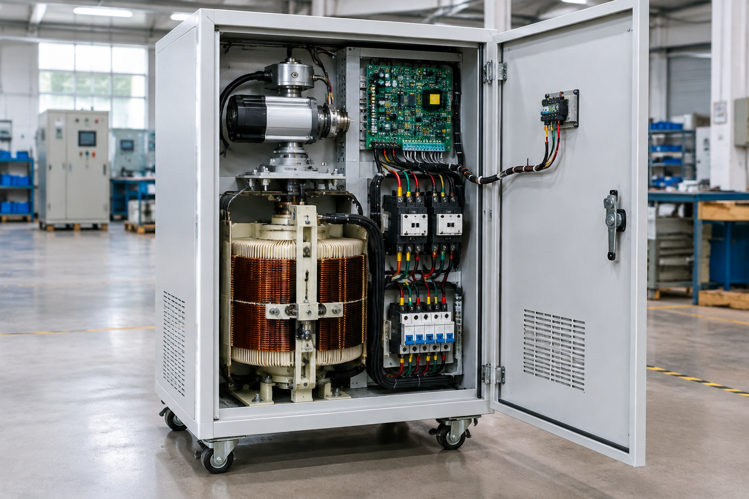
An automatic voltage stabilizer corrects an unstable supply by continuously sensing the output (or input) voltage, comparing it against a reference, and driving a correction element — a motorized variac, an electronic tap-changer, or a power converter stage — that adds or subtracts voltage through a series transformer until the output returns inside its regulation band. Understanding the components inside the enclosure is what lets a buyer compare stabilizers on substance: sensing resolution, correction speed, correction element duty, protection coordination, and thermal design. This guide explains each component group, its operating principle, and its specification points, then maps the three mainstream topologies against each other. It supports design and procurement discussions; final installation, code, safety, rating, and testing requirements must be confirmed with the responsible qualified engineer.
The component anatomy
| Component group | Function | Specification points that matter |
|---|---|---|
| Voltage sensing and reference | Measures output (or input) voltage and compares with the set reference band | Sampling point (true RMS versus average sensing), regulation band, response threshold |
| Control board | Decides direction and magnitude of correction; delays and protections logic | Time delay settings, under/over voltage cut-outs, protection coordination behavior |
| Drive mechanism | Moves the correction element (servo motor and geartrain) or switches taps (relays/semiconductors) | Duty rating, correction speed, mechanical life for motorized types |
| Correction element | Variable autotransformer (variac), tapped transformer with switchgear, or electronic power stage | Correction range (e.g. ±15% of nominal), current rating, technology wear mechanisms |
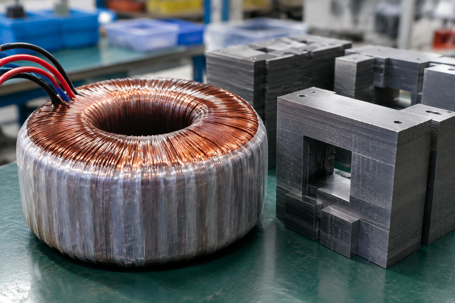
| Series/buck-boost transformer | Couples the correction voltage into the output circuit | kVA rating, insulation class, temperature rise class, isolation behavior |
| Protection and switching | Input/output breakers or MCCBs, over/under voltage cut-out, overload behavior | Breaking capacity suited to the installation fault level, bypass provisions |
| Bypass and isolation | Manual or automatic bypass route; maintenance isolation | Bypass continuity of neutral, switching procedure documentation |
| Indication and interfaces | Meters, status indication, alarms, optional remote monitoring | Alarm points, communication options, event logging where required |
Define the equipment boundary
Separate the transformer or stabilizer, connected equipment, enclosure, site conditions, and responsible engineering disciplines before selecting a configuration. Practical boundary items: does the stabilizer include input/output breakers or assume panel-mounted ones; is the bypass manual only; who sizes the cables; and where does the neutral connection regime sit — single- and three-phase stabilizers handle neutrals differently, and misdocumented neutral boundaries are a recurring installation fault.

Inputs to document
| Input | Why it matters |
|---|---|
| Equipment and interfaces | Sets layout, entries, clearances, control signals, power paths, and service access. |
| Environment and duty | Guides material, insulation, heat, moisture, corrosion, and exposure review. |
| Installation and maintenance | Controls mounting, isolation, access, labels, inspection, and service sequence. |
| Validation and records | Defines drawings, testing, oil or component records, and supplier documentation. |
Do not transfer a competitor performance, oil compatibility, protection, or certification claim to the complete project without project-specific evidence.
The three mainstream topologies compared
| Attribute | Servo-motor (variac) type | Relay tap-switching type | Electronic (SCR/power stage) type |
|---|---|---|---|
| Correction method | Motor-driven brush on a variac feeding a buck-boost transformer | Relays select fixed taps on the transformer | Semiconductor switching synthesizes correction voltage |
| Output smoothness | Continuous, stepless adjustment | Steps of one tap increment | Fast, effectively stepless within design range |
| Correction speed | Moderate — set by motor travel speed | Fast per step, limited by tap resolution | Fastest |
| Wear mechanism | Brush and thread wear — periodic service | Relay contact life | Semiconductor aging, surge susceptibility |
| Typical strength | High capacity, tolerant duty, favorable cost per kVA at size | Simple, economical at small ratings | Clean correction for sensitive loads |
| Watch-outs | Mechanical service intervals; brush quality varies | Step transients; tap resolution limits regulation tightness | Rating derating, harmonic behavior, surge environment |
Manufacturing plants with motor loads and moderate regulation needs commonly choose servo types at three-phase ratings; small commercial loads tolerate relay types; sensitive electronic production lines justify electronic correction. The honest comparison is against measured supply disturbance data, not catalog claims.
Thermal and enclosure engineering
The correction element and series transformer are the heat sources; enclosure sizing must account for their losses at rated load and worst-case input voltage, where correction duty is highest. Ventilation paths, fan duty where fitted, dust filters, and space heaters for condensation in humid sites belong in the specification. For outdoor or washdown environments, ingress protection and corrosion-resistant treatment move from options to requirements. The internal layout should separate power components from the control board, with service access that allows brush or relay replacement without disturbing the main connections.
Standards and verification
Stabilizers assemble certified components into a power assembly, so the verification conversation spans levels: the transformer inside follows the IEC 60076 series (with IEC 60076-11 for dry-type construction) or its IEEE C57 counterparts; the complete assembly can be verified against IEC 61439-1/-2 for low-voltage switchgear and controlgear assemblies, including temperature-rise verification; electromagnetic compatibility follows the IEC 61000 series environment classes; and installation falls under the local wiring rules — IEC 60364 contexts in most markets, NEC rules in North America. At acceptance, require: a routine test record per unit (dielectric, output voltage regulation across the stated input range at agreed load points, protection function checks), nameplate data matching the ordered ratings, and wiring drawings including the bypass scheme. Where a certificate references only components, treat the assembly-level verification as still open.
Frequently asked questions
Which component fails most often?
In servo types, the brush-variac interface and the motor drive train; in relay types, tap relays at high correction duty; in electronic types, the power stage after surges. All three failure modes are service items — ask the supplier for the spare parts list and replacement procedure before purchase, not after the first fault.
What correction range do I need?
From measurement: log supply voltage at the installation point over representative periods and size the range to cover the recorded extremes plus margin. Buying ±10% for a supply that swings ±20% produces a stabilizer that saturates at the worst moment.
Does a stabilizer protect against everything?
No — it corrects slow and moderate voltage deviations. It is not a surge protector, an isolation transformer, a frequency correcter, or a backup supply; those are separate devices with separate standards.
How do I size the kVA rating?
From the load’s true demand including inrush behavior of motors and transformers on the load side — the stabilizer’s correction element sees the inrush, so motor-heavy loads need generous headroom. A follow-up worth doing with your supplier: review the largest motor’s starting method together, because a soft starter or star-delta start on the load side can shrink the stabilizer rating the project must buy.
Can three-phase stabilizers handle unbalanced loads?
Depends on the design — three-phase regulated as a group versus independently regulated phases are different products for different unbalance profiles. State your phase unbalance data in the inquiry so the topology is chosen against it.
What maintenance does a stabilizer need?
Annual inspection of the correction element (brush wear, relay condition), connection torque checks, cleaning or filter replacement, and a functional check of protections — plus event-log review where logging is fitted, which often reveals supply problems the stabilizer has been silently correcting.
Procurement scenarios
For a plant buying its first large three-phase stabilizer (100 kVA class and above), order with a witnessed routine test including regulation verification at low, nominal, and high input points across the stated range, and one full set of spares for the correction element with the first unit — the spares cost a fraction of the downtime they prevent. For NEC-market delivery, confirm at inquiry whether the assembly needs UL 508A listing or a field evaluation path, since that choice adds weeks and should anchor the schedule. For multi-site rollouts of the same rating, qualify one design with a first-article test and then order against that test record — repeat orders referencing a witnessed baseline compress both price negotiation and delivery to a routine 4–8 weeks.
ElectricalCabinet.net builds automatic voltage stabilizers and power assemblies to order — our industrial voltage stabilizer selection guide covers the sizing path, and our dry type transformer page describes the transformer platforms these systems are built on.
 EN
EN