










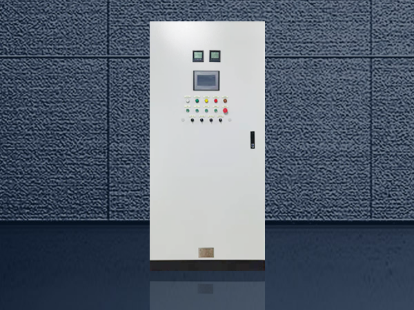
An industrial machine control panel is the electrical nerve center of a production machine: it distributes power to motors and actuators, executes the control logic that sequences the machine cycle, hosts the operator interface, and terminates every field signal the machine depends on. Defining one correctly means starting from the machine sequence and its interfaces — not from a generic component list. This guide sets out the inputs a project team should assemble, the boundaries between power, control, and safety responsibilities, and the standards that govern panel construction in different markets.
What an industrial machine control panel coordinates
A panel of this class brings together power distribution, control devices, PLC or relay logic, operator interfaces, field terminals, and machine interfaces. It may control a single machine or coordinate several connected units. The panel should be defined by the machine sequence and interfaces, not by a generic component list.
Start with the machine sequence
Describe the operating cycle, startup permissives, normal stop, emergency stop boundary, manual and automatic modes, maintenance or jog mode, fault response, and restart behavior. Identify which functions are in the panel, in a machine controller, in a drive, or in a separate safety system.
| Input | Questions to confirm |
|---|---|
| Machine stages | What actions occur in sequence, and what confirms each stage? |
| Motors and actuators | Which devices use starters, VFDs, valves, cylinders, or servos? |
| Sensors | Which position, pressure, level, speed, temperature, or presence signals are required? |
| Operator interface | What must the operator start, stop, adjust, acknowledge, or reset? |
| Interfaces | Which signals belong to upstream, downstream, robot, or line controls? |
| Environment | Is the panel exposed to dust, moisture, heat, vibration, or washdown? |
| Documentation | Which drawings, I/O lists, labels, and test records are required? |
Separate power, control, and safety responsibilities
The power section supplies connected loads: incoming disconnect, branch protection, starters or drives, and power wiring sized for the load schedule. The control section processes commands and feedback through a PLC or relay logic, at a lower voltage level, often segregated into its own wiring ducts and terminals. The safety system handles safety functions according to the approved machine risk assessment. These sections may share an enclosure, but their responsibilities should remain visible in the design documents.
Do not assume that a standard PLC panel includes a safety PLC, safety relays, guarding, risk assessment, or machine certification. Those items require a separate scope and engineering review. When a safety function is required, the specification should state who performs the risk assessment and who validates the safety circuit — the panel builder implements what the engineering documents define.
PLC, HMI, and drive interfaces
For every drive or actuator, define the command source, speed or position reference, run feedback, fault feedback, permissives, and stop behavior. Identify whether the interface is hardwired or networked and who supplies the program, parameter set, and commissioning. A hardwired interface is easier to troubleshoot and commission on small machines; a networked one reduces wiring on multi-axis systems but makes the cable, connector, and addressing plan part of the panel scope.

The HMI requirements should include status screens, alarms, user roles, recipes, trends, and reset rules only when they are part of the agreed scope. A panel quotation should not imply software or production optimization services that have not been confirmed.
Enclosure and maintenance inputs
Record ambient temperature, dust, moisture, vibration, mounting, cable entry, access side, internal heat sources, and maintenance space. The enclosure, cooling, filter, and cable-entry strategy must match the actual machine location. Do not infer a NEMA/IP rating or machine certification from a product photograph.
For a first estimate of enclosure size and cooling, the internal heat load from drives and power components can be checked with the enclosure temperature rise calculator; washdown or dusty areas usually push the selection from ventilated to sealed construction with closed-loop cooling.
Standards that govern machine control panels
Panel construction is standardized differently across markets, and the specification should name which regime applies:
- UL 508A — the North American standard for industrial control panels. It defines component selection, wiring practice, spacing, and the short-circuit current rating (SCCR) marked on the panel. A machine destined for a NEC-market plant commonly requires a UL 508A panel or an accepted field evaluation instead.
- NFPA 79 — the electrical standard for industrial machinery in the NEC market. It covers conductor sizing, disconnecting means, control-circuit voltage limits, e-stop behavior, and documentation expected alongside the panel.
- IEC 61439-1/-2 — the IEC framework for low-voltage switchgear and controlgear assemblies. It defines rated values, verification by testing or calculation, and the distinction between the original manufacturer and the panel builder. Machine control panels incorporating power distribution in the same enclosure are commonly verified against this series in IEC-market projects.
- NEMA 250 and IEC 60529 — enclosure protection references for the cabinet itself, defining the environmental tests behind type numbers and IP codes respectively.
A single physical panel cannot silently satisfy both regimes; the drawings, nameplate, and verification documents follow the standard the buyer names at order time.
Frequently asked questions
Can one panel control several machines?
Yes, when the machines share a sequence, a power system, and a clear interface boundary. The specification must still allocate one disconnect and protection hierarchy per machine where required by the applicable machine electrical standard, and define what happens to all machines on an e-stop or a power loss.
Follow-up: does a multi-machine panel need one emergency stop circuit for everything?
Not necessarily. The e-stop scope follows the machine risk assessment: it may cover the whole cell or isolate individual machines. What the panel must provide is the boundary defined in that assessment — contactors, safety relays or a safety PLC wired to the agreed stop category — not a default topology.
Should the PLC and drives share one enclosure?
It is common and economical, provided heat and noise are managed: drives add heat and electrical noise that can affect analog and communication signals. Physical segregation, separate power and signal routing, and a thermal check keep the combination reliable.
What short-circuit rating should the panel carry?
The SCCR or short-time withstand current must match or exceed the available fault current at the installation point, which the plant’s electrical engineer determines from the supply transformer and upstream impedances. The panel builder marks the rating achieved; specifying it after delivery is far more expensive than specifying it before construction.
Who supplies the PLC program?
By default the panel is delivered with the hardware and terminal wiring ready for program download; the machine logic, parameters, and commissioning are a separate scope agreed in writing. Some projects transfer a fully debugged program from the machine builder for the panel builder to load and verify point-to-point.
Information needed for quotation
Provide the process narrative, equipment list, motor and actuator schedule, sensor list, I/O list, operating modes, alarm matrix, HMI requirements, network interfaces, incoming power, enclosure environment, drawings, and responsibility matrix. State who supplies machine wiring, field devices, programming, commissioning, and acceptance testing. Related pages on this site — the PLC control cabinet and electrical control panel overviews — describe the corresponding product families.
Scope boundary
This guide does not define a universal PLC program, safety circuit, motor rating, communication protocol, or machine compliance result. It provides the planning inputs needed to define an industrial machine control-panel scope responsibly.
Ordering scenarios
A packaging-machinery OEM building to a North American specification typically orders machine panels in small first-article quantities — one or two units — built and documented to UL 508A with NFPA 79 documentation, holding series production until the first article passes the customer’s plant review. Here the binding constraints are the marked SCCR, the nameplate data, and delivery of the documented package, not only the wire list.
A production line upgrade in an IEC-market plant may instead order several panels at once against IEC 61439 verification documents, with the machine builder supplying programs and the panel maker responsible for assembly, wiring, and routine tests. In both routes, confirm the standard regime and the test-evidence boundary before the order, because retrofitting documentation or a higher fault rating after assembly is slow and costly.
ElectricalCabinet.net can use these inputs to route a machine-control enquiry to the appropriate PLC, VFD, enclosure, and control-panel capability.
 EN
EN