







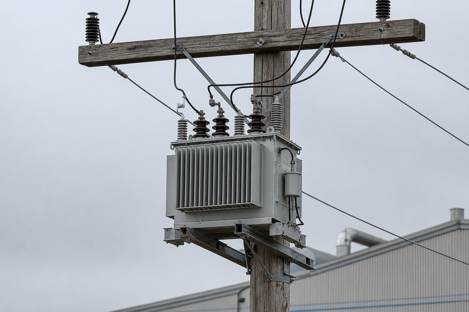
The pole-mounted transformer is the most numerous transformer format on earth: a cylindrical or compact tank bolted to a utility pole or platform, stepping distribution voltage down for a handful of customers, a farm, a pump station, or a small industrial site. Its design brief is brutal simplicity — survive outdoors for decades, unattended, through storms, temperature swings, and lightning — at a price that scales across thousands of units. This guide covers what a pole-mounted transformer is, how it is built, the standard ratings, and what matters at selection.
Construction: what is inside the tank
A conventional pole-mount is an oil-immersed (mineral oil, increasingly ester fluid) unit with:
- Core and coil assembly (CRGO or amorphous steel core; copper or aluminum windings) submerged in the fluid, which provides both insulation and cooling (ONAN — oil natural, air natural).
- Tank of welded corrosion-protected steel, often with cooling fins or a round “candle” profile for smaller ratings; designed for pole or crossarm mounting with hooks and lift provisions.
- HV bushings (one for single-phase; three for three-phase) with lightning-arrester coordination — arresters are the transformer’s real lightning defense and are normally specified alongside.
- LV bushings or a low-voltage enclosure with connection provisions for the service drop.
- Protection options: internally or externally fused (expulsion fuse, or backup current-limiting fuse for higher fault duties), and a surge arrester package.
- Taps: an off-circuit tap changer or link board, commonly ±2×2.5% steps, for trimming the ratio against local voltage conditions.
For single-phase rural networks, a common variant adds a secondary bushing to allow series/parallel primary connection — effectively two primary voltages from one unit. Where lighting or combined loads require it, three single-phase units can bank into a three-phase installation.
Standard ratings and what they mean
Pole-mounts follow distribution-standard rating series. Single-phase units commonly run 10–100 kVA as production standards (5–167 kVA across the market); three-phase pole units reach roughly 300 kVA, beyond which the format gives way to pad-mounted or substation formats. Primary voltages follow the local network — 7.2/12.47/13.2/13.8 kV class in North American practice, 11/20/24 kV or 33 kV in IEC markets — with secondaries of 120/240 V split or 208/480 V three-phase per local practice.
Sizing logic: a pole-mount is typically selected for projected load at end-of-life (20+ years out), not today’s peak — replacement of an overhead unit costs a line crew and an outage window, so slight oversizing is normal practice. Utilities also watch connected load diversity for multi-customer secondaries.
Standard ratings by format
| Format | Typical rating range | Common primaries | Typical service |
|---|---|---|---|
| Single-phase pole-mount | 10–100 kVA (5–167 across the market) | 7.2/12.47/13.8 kV (IEEE); 11/24 kV (IEC) | Rural service, farms, pump stations |
| Three-phase pole-mount | Up to ≈300 kVA | 12.47/13.8 kV; 11/20 kV | Small industrial and commercial loads |
| Three-unit bank | 3 × single-phase units | Per network | Open-delta or wye banks where needed |
| Above the pole-mount ceiling | 300+ kVA | — | Moves to pad-mounted or substation formats |
Selection inputs checklist
- Network data: primary voltage (and which of series/parallel connection for dual-voltage single-phase units), system grounding (effectively grounded vs ungrounded delta changes arrester and protection choices), available fault level.
- Load: kVA requirement and growth, load factor, motor starting duty (inrush affects both the transformer and fuse grading), phase requirements (or a three-unit bank plan).
- Environment: coastal or industrial corrosion class, altitude above 2,000 m (derating), ambient extremes, pollution level driving creepage requirements on bushings.
- Protection philosophy: fusecutting + arrester vs internal fuse; who coordinates with the upstream recloser.
- Standards regime: IEEE C57.12.20 / C57.12.00 (North American overhead practice) or IEC 60076 with local utility deviation sheets; DOE 2016 or Ecodesign efficiency documentation for the applicable market.
- Loss strategy: for lightly loaded rural feeders, amorphous-core options (typically 60–70% lower no-load loss) change the lifetime economics materially — ask for both core materials quoted.
Program scale and geography move the specification. On a 3,000-unit rural electrification order to IEC-market practice, three inputs deserve extra rigor because their cost of failure multiplies: the tank corrosion system where the network runs through coastal or high-pollution territory (the paint specification, hardware grade, and salt-spray evidence behind them decide whether the fleet’s twenty-year life holds or thins to twelve); the bushing creepage and pollution class for the same atmospheres; and the transport clamping that survives rural delivery roads. At this volume the routine test documentation regime is also a program decision — per-unit measured losses and withstand results batched per release region are what let a utility’s quality audits close without site visits.
What owners and specifying engineers verify on delivery
- Routine test report per unit (ratio, losses, impedance, withstand per IEEE C57.12.90 or IEC 60076-1).
- Tank finish and hardware rated for the corrosion environment; shipping damage inspection (pole tanks take transport hits that become leaks in service).
- Nameplate data completeness — the nameplate is the commissioning reference document; our companion guide walks through reading one field by field.
- Oil (or ester) dielectric test certificate, and for ester units, the handling differences at installation.
Mounting and safety notes
Installation belongs to qualified line crews under utility work rules — but specifiers influence safety through the design: mounting provision ratings (hooks, lift lugs, crossarm loads at the shipped mass), working clearances around HV bushings, LV connection access from pole position, and arrester lead lengths kept short (lead length directly degrades lightning protection). Nothing on this page substitutes for the utility’s construction standards.
FAQ
Why do utilities still use pole-mounts when underground networks exist?
Cost and repair speed. Overhead distribution with pole-mounts costs a fraction of underground per mile, faults are located and repaired faster, and the format has a decades-deep service and manufacturing ecosystem. Underground networks trade that for aesthetics and storm immunity.
Can a pole-mounted transformer serve a small factory?
Yes, within its rating ceiling — typically up to a few hundred kVA across one three-phase unit or a bank. Beyond that, or where the site needs metering compartments and multiple LV circuits, a pad-mounted unit with an LV cabinet is the better format.
What is the difference between a conventional and a “self-protected” pole-mount?
Self-protected designs integrate some protection functions (internal fusing, integral arrester provisions) to simplify the installation and coordinate protection within the unit. The choice follows utility standard practice rather than pure engineering preference.
How long do pole-mount transformers last?
Service lives of 30–40 years are common in temperate, benign environments; coastal corrosion and repeated lightning activity shorten that. The economic life question is usually decided by load growth outstripping capacity before the unit physically wears out.
How does coastal exposure change that arithmetic?
Chloride deposition attacks tank coatings, hardware, and seals — fleet lives shorten by years unless the corrosion class was specified honestly at purchase. The arrester strategy also carries more of the survival burden where lightning activity pairs with salt air.
What should a 3,000-unit IEC rural program specify to hold rated life at the coast?
A marine-class tank coating system with salt-spray evidence, stainless or appropriately plated hardware, bushing creepage matched to the pollution level, and transport provisions rated for rural roads. Then hold the fleet honest with per-unit routine test records batched by region — corrosion and loss drift are found in the paperwork long before the line crews see them.
Related reading
- pole-mounted transformers — our pole-mount product line and standard ratings.
- pad-mounted transformers — the format that takes over above the pole-mount ceiling.
- transformer kVA calculator — run the loading arithmetic behind rating selection.
Engineering note: this article is a construction and selection overview from ElectricalCabinet.net, a manufacturer of pole-mounted, pad-mounted, dry-type, and oil-immersed distribution transformers plus packaged substations and switchgear. Final selection, protection coordination, and installation practices must follow the serving utility’s standards and applicable electrical codes.
 EN