










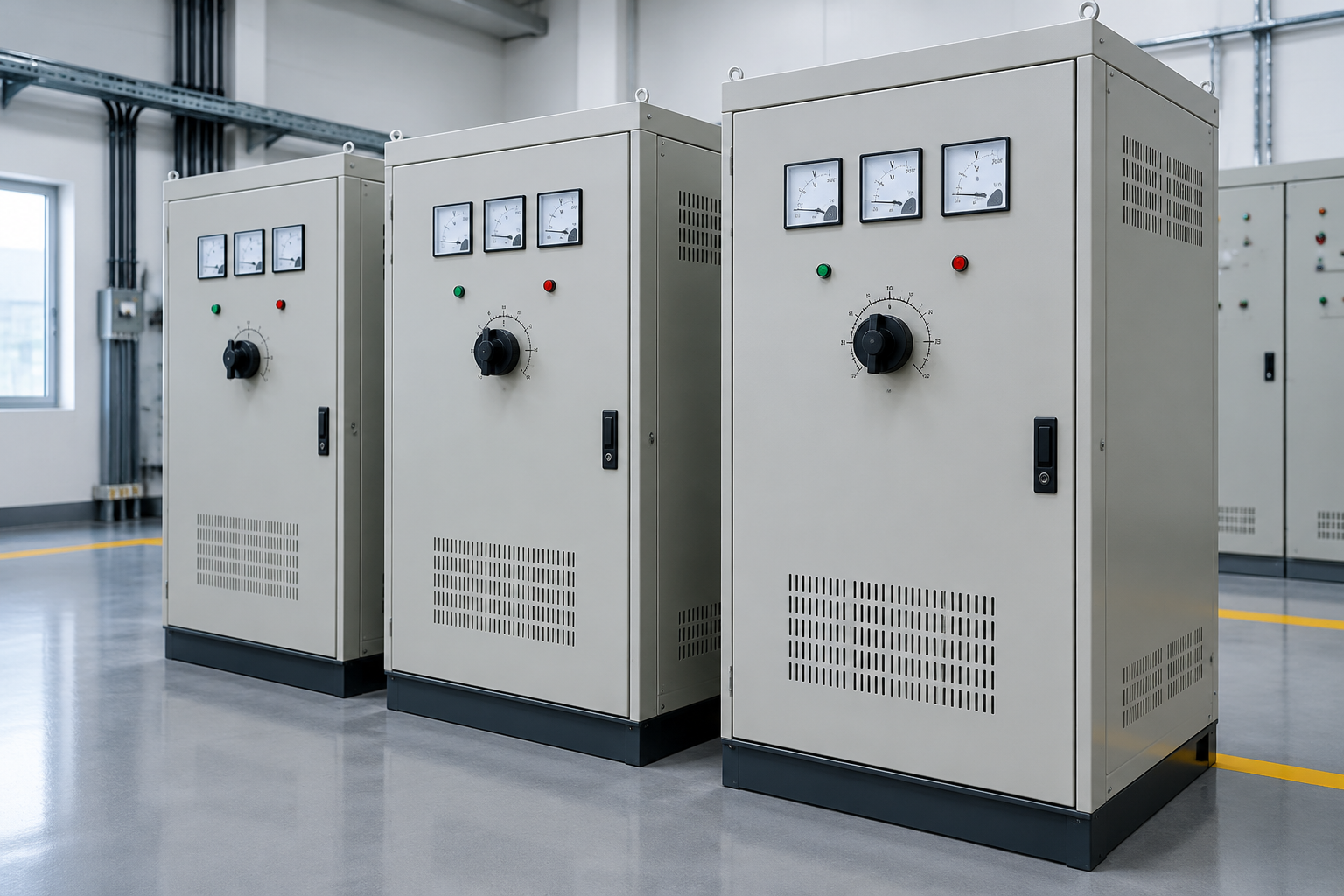
Selecting an industrial voltage stabilizer is a measurement-driven, seven-step process: measure the supply, define the correction range, list the load and its behavior, size the kVA with inrush headroom, choose the correction topology, match the enclosure to the environment, and verify at acceptance against the stated regulation promise. Skipping the first step — buying from nameplate guesswork instead of logged supply data — is why stabilizers get bought too small, with ranges that saturate exactly when the supply is worst. This guide runs the selection steps in order with the tables and checks that make each one objective. Final electrical ratings, protection, installation, testing, and qualified engineering requirements must be confirmed for the actual project.
The selection path, step by step
| Step | Input required | Output |
|---|---|---|
| 1. Measure the supply | Voltage log at the installation point over representative periods, worst season included | Real input range and disturbance profile |
| 2. Define correction range | Logged extremes plus margin | Required range (e.g. ±15%, ±20% of nominal) |
| 3. List the load | Per-equipment ratings, duty cycles, motor list with starting methods | Load profile and inrush behavior |
| 4. Size the kVA | Steady load plus starting current of the largest simultaneous motors | Stabilizer kVA with headroom |
| 5. Choose topology | Regulation tightness, correction speed, duty, service capability | Servo, relay tap-switching, or electronic correction |
| 6. Match enclosure and environment | Site conditions, heat, ingress, access | Enclosure specification and cooling design |
| 7. Define acceptance | Regulation band, load points, protection checks | Witnessed test scope and handover records |
Step 1-2 in practice: the measurement discipline
Log at the point where the stabilizer will connect, not at the substation up the road — cable drops and local loads shift the picture. Capture typical operating days and the worst seasonal conditions; note sags, swells, and their duration, because correction range and speed both follow from the disturbance profile. Then set the range with margin: a supply that has swung ±12% argues for a ±15% unit, not a ±10% one that corrects until it saturates and then passes the disturbance through. Record frequency stability too — a stabilizer does not correct frequency, and if the log shows frequency problems, this selection guide is not the document that solves them.
Step 3-4 in practice: sizing with inrush honesty
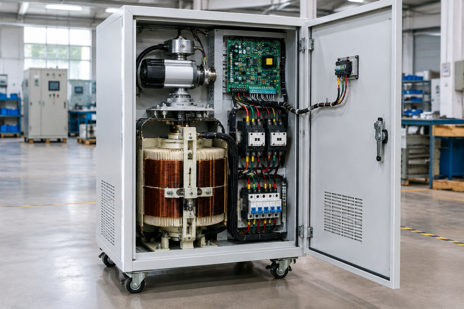
The load list drives the kVA: sum the steady-state demand with realistic diversity, then examine motor and transformer inrush — the largest motors starting together set the momentary current the correction element must survive without tripping or dropping regulation catastrophically. Soft starters or star-delta starting on the load side reduce the stabilizer rating a project must buy; direct-on-line starting of large motors inflates it. State the starting method in the inquiry. For mixed single- and three-phase loads, give per-phase data — independent-phase regulation versus group regulation is a design fork that per-phase measurement settles (see our three-phase transformer unbalanced loads guide for the unbalance context that feeds this decision).
Step 5: choosing among correction topologies
| Selection factor | Favors servo (variac) type | Favors relay tap-switching | Favors electronic type |
|---|---|---|---|
| Rating class | Mid to large three-phase industrial | Small commercial | Sensitive electronic loads |
| Regulation smoothness | Stepless correction | Stepwise per tap | Effectively stepless in range |
| Correction speed need | Moderate | Fast per step | Fastest |
| Service model | Brush/gear service intervals acceptable | Simple relay service | Surge environment controlled |
| Cost per kVA at size | Favorable at capacity | Lowest at small size | Premium |
The component-level anatomy of each topology — sensing, control, drive, correction element, series transformer, protection, bypass — is detailed in our automatic voltage stabilizer components guide.
Step 6: enclosure and environment
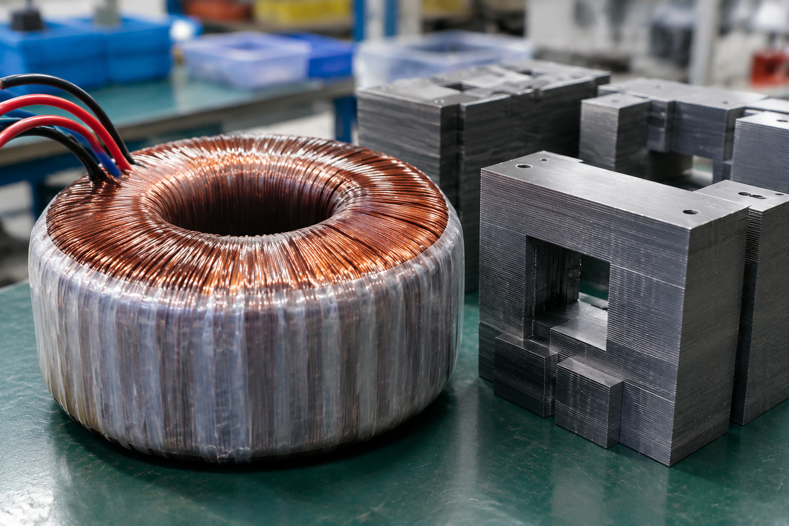
Heat is the engineering constraint: the correction element and series transformer are the loss sources, worst-case at the extremes of input voltage where correction duty peaks, and enclosure sizing follows that heat plus ambient. Dust, moisture, and corrosion environments move ingress protection and material treatment from optional to specified; outdoor and washdown sites demand it. Layout separates power and control sections and preserves service access to the correction element — the component the maintenance schedule will visit. Ventilation paths, filter maintenance, and condensation heaters for humid sites are specification line items, not site improvisations.
Define the equipment and site boundary
Record source and load conditions, operating modes, environment, mounting, cable routes, access, maintenance ownership, and interfaces between the equipment, cabinet, installer, and operator.
Inputs to document
| Input | Why it matters |
|---|---|
| Electrical duty | Voltage, current, frequency, fault level, load type, switching or regulation duty, and protection assumptions. |
| Site and enclosure | Indoor or outdoor exposure, moisture, dust, corrosion, temperature, clearances, cooling, cable entry, and service space. |
| Controls and operation | Modes, alarms, bypass or isolation, interlocks, local interfaces, remote signals, labels, and operator sequence. |
| Verification and handover | Drawings, nameplate data, inspection points, test records, settings, manuals, spares, and maintenance instructions. |
Step 7 and the standards context
At acceptance, the stabilizer’s regulation promise becomes a test: routine verification should demonstrate output within the stated band across the stated input range, at agreed load points, with protection functions (over/under voltage cut-outs, overload behavior) checked and recorded, and nameplate data matching the ordered specification. The assembly-level framework for that verification is IEC 61439-1/-2 in IEC markets (assembly verification including temperature rise) with the transformer inside following IEC 60076 family construction and the North American path running through the UL framework with NEC installation rules — the same layered compliance picture as any power assembly, with regulation performance as the additional product-specific test.
Review before release
- Separate confirmed project data from assumptions and vendor options.
- Check the boundary between equipment, enclosure, protection, cabling, and site installation.
- Record open decisions and acceptance evidence before procurement or fabrication.
Do not copy competitor certification, protection, performance, or availability claims without project-specific evidence.
Frequently asked questions
How much kVA margin should I add?
Margin follows inrush, not nervousness: with motor starting methods documented, 20–25 percent above steady demand typically covers mixed industrial loads; direct-on-line starting of large motors can demand much more. Size from the load list, not a rule of thumb.
One big stabilizer or several small ones?
Several, when the loads split into sensitive electronics versus heavy motors — each gets the topology it needs and faults stay local. One, when the whole plant shares the same disturbance profile and service simplicity wins.
What regulation band is realistic?
Servo types regulate continuously within a percent-class band; tap-switching types within their step resolution; electronic types tighter still. Tighter than the load actually requires buys cost, not benefit — check the equipment tolerance tables first.
Does the stabilizer protect my equipment from lightning?
No — surge protection is a separate device class ahead of it. Stabilizers and surge protectors are complementary stages in a power-quality scheme, not substitutes.
Should the bypass be automatic?
For processes that value continuity over regulation, automatic bypass on stabilizer fault keeps the load fed (unregulated) — for loads where bad voltage is worse than a stop, manual bypass with alarm is the right choice. The follow-up question to answer in the design review: what does the load experience during bypassed operation, because that answer — not the switch’s catalog description — sets the right configuration.
How often should settings and performance be re-verified?
Annually with the correction-element service, and after any major supply or load change — the supply that justified the selection may drift, and the unit should be re-ranged against new measurement, not run on old assumptions.
Is a stabilizer the same as a power conditioner or voltage regulator?
The terms overlap but are not identical. Automatic voltage regulation (AVR) is the function every stabilizer performs — holding output in a band while input swings — and a power regulator is the loose retail name for any device doing that job. A power conditioner is broader: power conditioning covers voltage regulation plus surge clamping, noise filtering, and sometimes isolation in one box, so power conditioners may or may not include true regulation — read the regulation spec on the datasheet rather than the label. If the log shows sags and swells you need regulation; if it also shows transients, add a separate SPD ahead of it.
Procurement scenarios
For a plant with a logged supply swinging beyond a first stabilizer’s range, order the replacement with the witnessed regulation test across the full stated range and step the old unit down to a less-critical bus — the measurement that exposed the error becomes the acceptance criterion for the fix. For a new installation feeding VFD-heavy production, specify independent-phase regulation from the start and order the spare correction-element set with the first unit. For NEC-market delivery, fix the compliance path (UL 508A assembly versus field evaluation) at order stage, since certification timing — not manufacturing — typically sets the delivery date for this equipment class.
ElectricalCabinet.net builds industrial stabilizers and complete power assemblies to order — the component anatomy guide and the stabilizers, regulators, and transformers comparison frame the same decision from the inside and the outside.
 EN
EN