










Solar power switchgear is part of the electrical distribution and protection arrangement that connects photovoltaic generation, inverters, transformers, collection equipment, storage interfaces, or the grid. The correct configuration depends on the project topology, voltage levels, protection philosophy, environmental conditions, and utility or customer requirements — the word “solar” describes the application context, not a standard product. This guide organizes the inputs an engineering team should assemble before asking a supplier to quote PV distribution equipment.
This article is an application-planning guide. It does not claim a specific solar project delivery, equipment rating, grid approval, or certification for any product shown on this website.
Define the solar system boundary first
Before selecting switchgear, describe which part of the solar plant the equipment serves. A project may contain DC collection, inverter outputs, low-voltage distribution, medium-voltage collection, transformer interfaces, auxiliary power, storage, or a grid interconnection point. Each of these boundaries implies different equipment: what collects inverter outputs at low voltage has little in common with what switches a medium-voltage feeder to the interconnection transformer.
The inquiry should state:
- the equipment boundary and one-line function;
- inverter, transformer, collection, and feeder interfaces;
- operating modes, isolation requirements, and maintenance access;
- monitoring, metering, protection, and communication expectations; and
- the utility, owner, engineering, and installation responsibilities.
Do not infer a suitable switchgear arrangement from the words “solar switchgear” alone.
Common switchgear roles in PV distribution
Inverter output and collection
Switchgear may be used to collect inverter outputs or distribute power to a transformer or downstream system. Confirm the equipment arrangement, feeder count, protection functions, cable interfaces, and maintenance access for the actual design. The number of inverter feeders, their ratings, and whether reconfiguration between strings is required all shape the lineup before any environmental question is raised.
Transformer and medium-voltage interface
Where a transformer connects the PV collection system to a higher-voltage distribution network, the project must define the switching, protection, metering, grounding, and cable termination requirements. The applicable voltage, fault, and coordination information must come from the responsible electrical design. Cross-checking the transformer size against the generation and loading assumptions is a standard step here — the transformer kVA calculator supports that first-pass check.
Grid interconnection
The interconnection point can require utility-specific protection, metering, isolation, communication, and documentation. The supplier should receive the approved project requirements rather than being asked to infer them from a generic solar equipment label. Interconnection requirements differ between utilities and between markets; they are inputs to the equipment specification, never outputs of it.
Auxiliary and balance-of-plant systems
PV plants also contain control power, tracking, monitoring, HVAC, lighting, and other auxiliary loads. These may require separate control or distribution arrangements that should be described in the project scope. Auxiliary systems are frequently the last items specified and the first to reveal an incomplete single-line diagram.
Inputs for switchgear selection
Organize the inquiry around the actual electrical and site conditions.
| Input area | Questions to define |
|---|---|
| Electrical topology | What equipment connects upstream and downstream? |
| Power sources | Which inverters, transformers, storage units, or auxiliary sources are included? |
| Protection | Which protection, isolation, metering, and coordination requirements apply? |
| Environment | What outdoor exposure, dust, humidity, temperature, corrosion, and access conditions exist? |
| Cabling | How do cables enter, terminate, route, and get maintained? |
| Monitoring | Which status, alarms, meters, and communication interfaces are required? |
| Documentation | Which drawings, inspection records, manuals, and utility submissions are needed? |
The final equipment arrangement must be checked against the project one-line diagram and approved requirements.
Outdoor and environmental considerations
Solar equipment is often installed outdoors or in locations with high exposure to sunlight, moisture, dust, temperature changes, and maintenance activity. Review enclosure construction, mounting, access, cable entry, corrosion strategy, condensation, heat, and service clearances together.
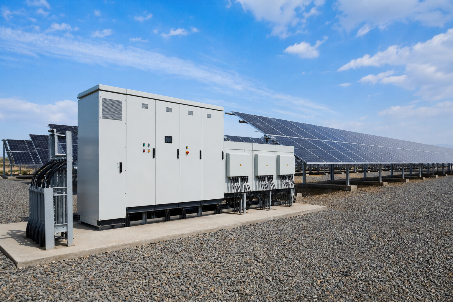
If a NEMA or IP classification is required, confirm it for the exact model and configuration. A solar installation image or enclosure material does not prove an environmental rating. Sites near coastlines or agricultural zones should flag the corrosion question early — the difference between standard and enhanced corrosion protection is an order-time decision, not a field retrofit. The NEMA-to-IP converter helps translate between rating languages once the specification names one system.
Standards context for PV distribution equipment
- IEC 62271 — the IEC series for high-voltage switchgear and controlgear, referenced by the medium-voltage collection and interconnection sections of a PV plant; the equipment ratings and type-test evidence follow this family.
- IEC 61439 — the IEC framework for low-voltage assemblies, applied to the inverter-output collection and auxiliary distribution panels inside the plant boundary.
- IEEE C37 — for North American projects, the switchgear and circuit-breaker ratings in the collection and interconnection chain reference this standards family rather than the IEC series.
- UL 508A / NFPA 79 — where plant auxiliary and control panels are industrial control panels in the NEC market, these standards govern their construction and machine-level wiring documentation.
Utility interconnection standards and grid codes are jurisdiction-specific requirements layered on top of the equipment standards; they are determined and confirmed by the responsible engineer and the authority having jurisdiction, not by an equipment catalogue.
Protection, isolation, and documentation boundaries
The project team should identify how equipment is isolated, which devices provide protection, how status and alarms are monitored, and which party supplies the settings or coordination study. Do not publish or use an unreviewed single-line diagram as an installation instruction.
The supplier should state assumptions, exclusions, and the evidence supporting any requested compliance claim. Utility or grid requirements must be confirmed by the responsible engineer or authority.
Solar switchgear quotation checklist
Before requesting a quotation, include:
- approved system topology or one-line function;
- inverter, transformer, feeder, storage, and auxiliary interfaces;
- protection, metering, isolation, and monitoring requirements;
- site, environment, mounting, cable-entry, and maintenance conditions;
- utility, owner, and engineering documentation requirements; and
- responsibility boundaries for design, installation, testing, commissioning, and approval.
For broader context, see the medium-voltage switchgear guide and air-insulated vs gas-insulated switchgear comparison. Use the switchgear product routes to review product scope, then confirm solar applicability for the actual model.
Frequently asked questions
Is solar switchgear different from ordinary switchgear?
The switching and protection principles are the same; the differences are in the application context — bidirectional power flow possibilities, generation-side fault contributions, utility-specific interconnection requirements, and outdoor environmental exposure. Those are specification inputs, not a different physics.
Follow-up: does bidirectional flow require special equipment?
It requires equipment whose ratings and protection scheme account for the actual direction and magnitude of fault and load currents, as established by the project study. What it does not require is a mystery product category — a lineup specified against the correct study handles the duty.
Can the same lineup serve collection and interconnection?
Sometimes at medium voltage, if the protection, metering, and isolation requirements are compatible and the utility accepts the arrangement. Often the interconnection point gets its own section with utility-mandated devices. The one-line diagram and the utility agreement decide, not equipment preference.
What environmental rating do outdoor PV lineups need?
It follows the site: rain, dust, solar gain, humidity, and corrosion exposure together define the target, confirmed for the configured assembly. Coastal and desert sites commonly land on different answers for the same nominal product family.
Who supplies the protection settings?
The project’s protection study — usually owned by the engineering firm with utility input at the interconnection — defines them. The equipment supplier implements and documents the agreed settings; a supplier proposing settings without the study is making an assumption worth challenging.
Final review
Solar switchgear selection should connect the PV topology, protection and isolation philosophy, site environment, monitoring interfaces, and documentation requirements. Treat “solar” as an application context, not as proof of a particular equipment configuration or project capability.
Ordering scenarios
A utility-scale EPC contractor typically orders the first collection and interconnection sections as a pilot batch — enough to energize one or two inverter blocks — holds the series order until the utility witnesses the interconnection tests, then releases the remaining lineups against the frozen design. The binding constraints are the utility approval cycle and the protection-setting freeze, because each day of setting review extends the energization path regardless of equipment readiness.
A commercial-rooftop developer operating across two regulatory regions should fix the equipment regime per destination at order time: the IEC-market site references IEC 62271 and IEC 61439 evidence for its sections, the North American site references the IEEE C37 equipment family, and the auxiliary panels follow UL 508A where applicable. Splitting the first order — one pilot lineup per regime with its own documentation package — keeps the bulk order from inheriting the wrong market’s evidence trail.
 EN
EN