







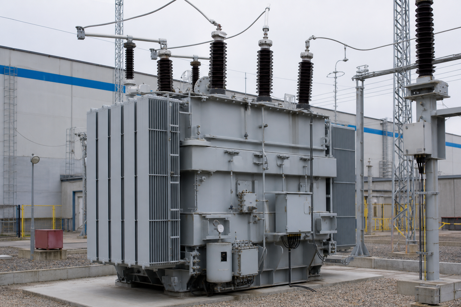
“Medium voltage” is the band where industrial facilities, infrastructure, and distribution networks actually live — roughly 1 kV to 38 kV class in North American practice (up to 36 kV in IEC markets). A medium voltage transformer is any transformer whose primary works in that band: the step-down units feeding plants and buildings, the dry-type units in electrical rooms, the pad- and pole-mounted units on the network. This guide covers the voltage classes, what changes electrically as you climb them, and the selection inputs that matter.
The voltage class map
| Class (nominal) | IEC highest-voltage-for-equipment | Common usage |
|---|---|---|
| 3.3 / 6.6 kV | 3.6 / 7.2 kV | Older industrial plants, mining |
| 10 / 11 kV | 12 kV | Distribution standard in many IEC markets |
| 13.8 kV (13.2/12.47) | 15 kV class | North American distribution and industrial |
| 20 / 24 kV | 24 kV | Distribution in parts of Europe, Asia |
| 33 kV | 36 kV | Sub-transmission feeders, large industrial infeeds |
| 34.5 kV | 38 kV class | North American heavy industrial, wind/solar collection |
Two consequences flow from the class you select: the insulation system (dielectric design, clearances, and the impulse rating) and the switchgear and cable ecosystem around the transformer must all match the same class.
What changes at medium voltage that did not matter at LV
- Insulation levels become a specified trio. Rated power-frequency withstand, rated impulse (lightning) withstand — the BIL — and the highest voltage for equipment are all contractual values, per IEC 60076-3 (or IEEE C57.12.00 tables). Our companion guide covers BIL in depth; the short version: overhead-fed units live and die by impulse level, and underspecified BIL is a latent lightning casualty.
- Vector group / connection discipline. The winding connection (Dyn11, YNd, Dzn, etc.) determines neutral availability, earth-fault behavior, paralleling compatibility — see our vector group guide.
- Impedance becomes a system parameter. MV transformer impedance (commonly 4–8% on rating for distribution-class units; project-specific beyond) sets the LV fault level, which sizes every downstream breaker. Choosing impedance is a coordination decision, not a vendor default.
- Testing depth increases. Induced and separate-source withstand, partial discharge measurement on MV dry-type units, impulse testing where specified, sound level where the room demands it.
- Termination engineering. Cable boxes, separable connectors (elbows), or bushings must coordinate with cable types and clearances — a frequent commissioning battleground between transformer, cable, and civil trades.
Construction options across the band
- Oil-immersed (ONAN and up). The economic default for outdoor and utility duty — pole-mounts, pad-mounts, substation units. Mineral oil or ester fluid; conservator or hermetically sealed construction.
- Dry-type (VPI/cast resin). The indoor standard — electrical rooms, infrastructure, offshore. Class F/H insulation, C/E/F classifications per IEC 60076-11 for climate, environment, and fire behavior.
- Specialty MV units. Drive isolation transformers for MV drives, furnace and rectifier transformers, and earthing/grounding transformers — each with duty-specific standards supplements.
Selection inputs to record
- Electrical: kVA, primary/secondary voltages (and taps: typical ±2×2.5% off-circuit), phases, frequency, vector group, impedance, BIL and power-frequency withstand, losses with tolerance.
- Installation: indoor/outdoor, ambient profile, altitude above 2,000 m, corrosion class, seismic zone where applicable, room ventilation for dry-type heat rejection.
- Load: harmonic content (k-factor or derating for dry-type), motor starting duty, unbalance, growth margin.
- Protection interface: fuse or relay scheme upstream, inrush withstand coordination (see our inrush guide), earth-fault philosophy tied to vector group.
- Compliance: IEC 60076 series or IEEE C57 series design basis; DOE 2016 / EU Ecodesign efficiency documentation; UL recognition where the AHJ requires.
Site extremes and order size sharpen the paperwork. On a 50-unit order for a North American project sited at high elevation, the insulation inputs stop being boilerplate: above the 2,000 m line the cooling capacity and external insulation derating must appear as stated, verified design values on every quotation — and where the units are overhead-fed, the BIL selection should be reviewed against the exposure with the arrester coordination, not inherited from a previous project in a different geography. At 50 units the documentation that locks these inputs is per-unit routine test records citing the IEEE C57 test codes, delivered with each shipment; a family datasheet in the file does not survive an AHJ review of an installed fleet.
Common specification errors we see
- BIL copied from a different voltage class project — the single most repeated MV documentation error.
- Impedance left as “manufacturer standard,” then downstream switchgear is sized on assumed fault levels.
- Dry-type units specced without climate/environment class, then installed in humid rooms without heater provisions.
- Cable box interfaces left undefined between transformer and cable suppliers — settle termination responsibility in the purchase contract.
FAQ
Where does medium voltage end and high voltage begin?
Conventions differ: IEC practice treats 1–36 kV as MV (with 52 kV equipment voltage a common ceiling), North American utility practice runs the MV/ HV boundary loosely around 34.5–69 kV. The practical significance is regulatory and standards routing, not physics.
Dry-type or oil at medium voltage — which is standard?
Indoor near occupied space: dry-type (cast resin where fire classes matter). Outdoor and utility duty: oil/ester for economics. The dividing line is the building wall and the fire code, not a universal rule.
How does a high-altitude site shift the specification inputs?
Two corrections apply above the ~2,000 m derating line: reduced cooling capacity in thinner air (nameplate kVA assumes reference conditions) and derated external insulation. Both belong on the datasheet as verified values per unit — and the correction math differs between dry-type and oil constructions, so it cannot be applied generically after purchase.
For a 50-unit North American order, which documentation locks those inputs per unit?
The routine test report per serial number citing IEEE C57 test codes (with measured ratio, losses, impedance, withstand), plus the stated derating values and BIL with the governing table reference. Where the AHJ requires UL recognition, that listing documentation rides with each shipment — not as a program-level letter.
Do MV transformers need impulse (lightning) testing?
The impulse withstand rating is a design and type-test value; routine impulse testing applies where specified (common for units on overhead exposure). What always matters at specification time is that the BIL column matches the exposure: overhead-fed and outdoor units justify higher impulse levels than cable-shielded indoor infeeds.
Related reading
- medium voltage transformers — our MV transformer product line.
- dry-type transformers — the indoor MV build path for industrial substations.
- kVA calculator — the rating step once the voltage class is fixed.
Engineering note: this article is a class and selection overview from ElectricalCabinet.net, a manufacturer of medium voltage transformers (dry-type and oil-immersed), packaged substations, and LV/MV switchgear assemblies. Final voltage class selection, insulation coordination, and protection design require qualified engineering review against the applicable installation codes.
 EN