











Explain EMI and EMC boundaries for electrical enclosures using sources, coupling paths, bonding, cable entry, segregation, grounding, testing, and records. Confirm final electrical ratings, code, safety, installation, testing, and qualified engineering requirements for the actual project.
EMI (electromagnetic interference) is the phenomenon: unwanted electromagnetic energy emitted by, or imposed on, equipment. EMC (electromagnetic compatibility) is the achieved state: equipment that neither emits intolerable disturbance nor misbehaves under the disturbance present in its environment. The enclosure sits between the two. A conductive, well-bonded enclosure attenuates fields that would otherwise couple into internal wiring; at the same time, every cable entry, seam, and window is a leakage path that can undo the shielding. Enclosure EMC work is therefore mostly work on apertures and bonding – the metal itself is the easy part.
How enclosures interact with electromagnetic fields
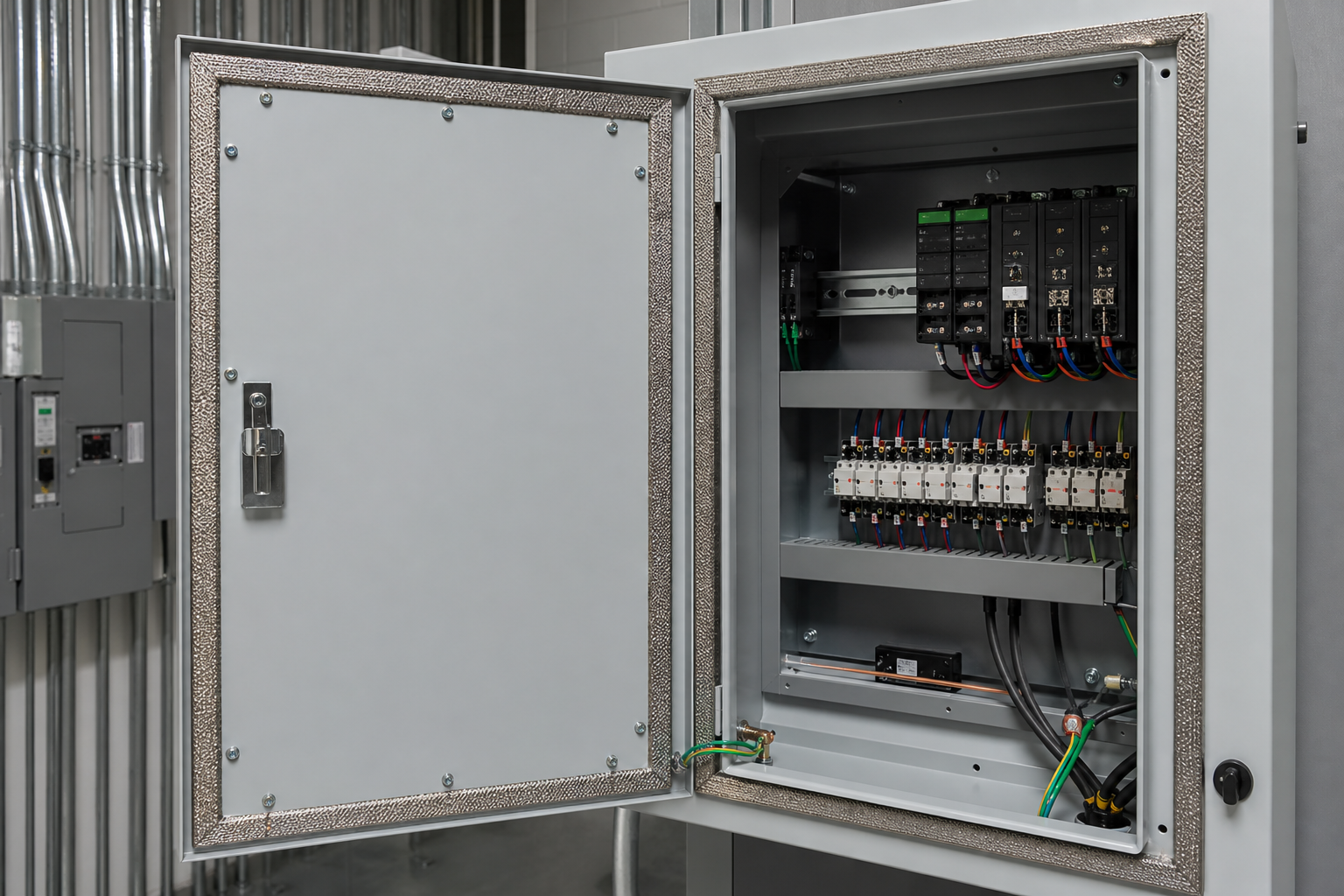
A continuous conductive enclosure behaves as a Faraday-style barrier: incident fields induce currents in the skin that oppose penetration. Performance degrades predictably at three kinds of discontinuity:
| Leakage path | Mechanism | Design countermeasure |
|---|---|---|
| Seams and door joints | Contact points act as slot antennas; longer slots leak lower frequencies | Conductive gaskets, many fasteners, overlapping folded joints |
| Display and vent openings | Apertures pass wavelengths larger than the opening | Bonded wire mesh or honeycomb vent panels; shielded window films |
| Cable entries | Cables carry disturbances in and out, bypassing the shield entirely | 360° screen termination, shielded glands, filters at the boundary |
The cable-entry row is decisive: an unfiltered, unterminated cable defeats a perfectly good shield, which is why EMC enclosure planning starts at the cable schedule, not the cabinet wall. Grounding and bonding close the system – shield effectiveness exists only when induced currents have a low-impedance path back to the reference, and painted, anodized, or oxidized joints are insulators until designed otherwise (toothed washers, conductive finishes, bonding straps).
Define the equipment boundary
Record the equipment, conductors, operating modes, enclosure, environment, access, maintenance ownership, and interfaces between the supplier, cabinet builder, installer, and operator.
| Input | Why it matters |
|---|---|
| Electrical and process duty | Voltage, current, load, fault assumptions, control signals, switching or motor duty, and operating sequence – drives and switching devices are typical sources; analog and communication lines are typical victims. |
| Environment and enclosure | Indoor or outdoor exposure, moisture, dust, corrosion, hazardous-area information, heat, mounting, and cable entry – the environment sets what the enclosure must already survive before EMC is layered on. |
| Access and maintenance | Isolation, lockout boundaries, door or withdrawal clearance, labels, replacement sequence, tools, and service records – every gasket disturbed in service changes shield continuity until restored. |
| Verification and handover | Drawings, parts list, settings, inspection points, test results, manuals, training, and open decisions. |
Separate confirmed data from assumptions and do not copy competitor certification, safety, fault, or performance claims without evidence for the actual project.
Standards and testing landscape
- IEC 61000-6-2 / -6-4. Immunity and emission requirements for equipment in industrial environments – the baseline EMC framework an enclosure-based assembly is usually assessed against.
- IEC 61000-4-3 / -4-4 / -4-6. Immunity test methods (radiated RF, electrical fast transients, conducted RF) that define what the equipment inside must tolerate.
- CISPR 32 / EN 55032 (and CISPR 11 for industrial, scientific, and medical equipment). Emission limits applied to the finished equipment; enclosures influence results through shielding and cable treatment.
- Shielding performance measurement. Practices such as IEEE Std 299 define shielding-effectiveness measurement for enclosures and rooms – the method behind any dB figure quoted for a shielded cabinet.
- Material-level evidence. Surface-transfer-impedance or conductivity data for coatings and gasket materials; UL 94 and IEC 60529 remain the parallel safety/ingress files, and combining conductive gaskets with ingress gaskets is a joint design task, not a bolt-on.
Notably, neither an IP code nor a NEMA type says anything about EMC. A NEMA 4X cabinet is superbly watertight and electromagnetically transparent until its seams and entries are bonded – the rating families answer different questions.

Frequently asked questions
Does a metal enclosure automatically provide EMC shielding?
It provides a shield body; performance comes from the discontinuities. Doors, seams, windows, and especially cables determine the result. A steel cabinet with an unfiltered cable passing through an oversized hole is a shield with the door open.
What is the difference between EMI shielding and earthing?
Earthing provides reference and fault paths; shielding intercepts fields. They meet at bonding – a shield that is not bonded cannot drain intercepted currents, and a bond with paint under it is not a bond.
How are cable screens best terminated at the enclosure?
At the boundary, 360 degrees – via shielded glands or EMC cable-entry frames – not pigtailed to a terminal. The pigtai transition converts the screen into an antenna precisely where it crosses the shield wall.
Do plastic enclosures exclude EMC control?
No, but the options change: conductive coatings, metallized plastics, and internal sub-shields recover much of the performance, at the cost of process control and evidence for coating continuity.
Is EMC tested at the enclosure level or the system level?
For compliance, at the equipment or system level – emission limits and immunity requirements apply to the finished apparatus, not an empty box. Enclosure-level shielding measurements (attenuation across a defined frequency range) are design evidence used to predict that performance, and their value depends on the tested configuration matching the delivered one.
When does a project need a formal shielding test?
When the environment or the equipment is aggressive – high-power drives near sensitive instrumentation, radio sites, medical or lab contexts – and the contract makes dB-level performance a requirement. The measurement method and the enclosure’s configuration at test time must then be documented.
Ordering scenarios
A mill-automation project housing 40 drive and I/O cabinets beside rolling-mill instrumentation would specify bonded seams and conductive door gaskets, EMC cable-entry frames with gland plates bonded to the body, internal segregation between power and signal compartments, and assembly-level EMC test evidence per IEC 61000-6 immunity requirements for the delivered configuration. A laboratory-equipment OEM shipping 150 compact metal enclosures beside sensitive receivers takes the component path: conductively finished chassis, shielded connectors with 360° termination, filtered power entries, CISPR 32/EN 55032 emission evidence, and a documented bonding diagram in the manual – so that installation crews reproduce the tested geometry rather than improvising it.
 EN
EN