







Applying PLC control to manufacturing machinery is a sequence-engineering exercise: the machine’s steps, transitions, permissives, and failure modes are captured in a control narrative, mapped onto an I/O list, guarded by a safety boundary, and executed from a control cabinet engineered for the machine’s environment. Whether the machine is a press, packaging line, machining cell, or assembly station, the planning inputs are the same — machine sequence, I/O, safety functions, network interfaces, cabinet layout, and service requirements. This guide walks those inputs in engineering order so the PLC program and panel arrive as a designed system rather than an accumulation of parts. It supports design and procurement discussions; final installation, code, safety, testing, cybersecurity, and qualified engineering requirements must be confirmed for the actual project.
The machine-control design flow
| Stage | Engineering activity | Deliverable |
|---|---|---|
| Sequence definition | Steps, transitions, permissives, modes (auto, manual, step, maintenance) | Control narrative and state descriptions |
| I/O engineering | Every sensor, actuator, drive, and analog signal listed with electrical data | I/O list with types, ranges, and normal states |
| Safety boundary | Risk assessment identifies hazards; safety functions specified with required performance | Safety requirements specification per ISO 13849 / IEC 61508 |
| Architecture | Controller, remote I/O, drives, network selection; cabinet and HMI placement | Architecture drawing and cabinet general arrangement |
| Implementation | Program per IEC 61131-3 languages, panel build per market standard | Code under version control; panel with BOM and schematics |
| Verification | Simulation or bench FAT, then site SAT with recovery scenarios | Signed FAT/SAT records with test matrices |
Reading the I/O list like an engineer
An I/O list is the contract between machine and controls. Each digital input carries its device, function, signal state convention (energized-to-trip or de-energized-to-trip), and normal state; each output its load type and rating; each analog point its range, scaling, and engineering units. Debounce and filtering for noisy sensors, spare points (commonly 10–20 percent per card type for machines expected to evolve), and terminal mapping that the maintenance technician can trace are design decisions, not clerical ones. Drives add a layer: command source, reference signal, run and fault feedback, and stop category behavior must each be defined — a VFD’s response to a network failure is a design choice that belongs in the specification.
The safety boundary — drawn, not assumed
Machinery safety starts with the risk assessment, which identifies hazards and defines safety functions: emergency stop, guard door interlocking with or without lock, safe stop of drives, two-hand control, light curtain interruption behavior. Each function is assigned a required performance level (ISO 13849 PL a–e) or safety integrity level (IEC 61508 SIL), and the implementation — safety PLC, safety relays, certified components, validated wiring — must meet that requirement. The boundary matters commercially: safety functions owned by the machine builder versus the controls integrator must be named, and the validation evidence (stop-time measurements, category verification calculations) delivered with the machine. Interlocks in standard PLC code are process protection; they are not safety functions unless engineered and validated to the safety standard.
Define the system boundary
Separate the control cabinet, field devices, PLC or supervisory software, networks, site conditions, and responsible engineering disciplines before selecting a configuration. Machine projects add recurring boundary decisions: field wiring by machine builder or panel supplier; HMI supplied with machine or by plant standard; program source code ownership; and who writes the recovery procedures operators actually use.

Inputs to document
| Input | Why it matters |
|---|---|
| Equipment and interfaces | Sets layout, entries, clearances, signals, power, network paths, and service access. |
| Process and environment | Guides sensor choice, material, heat, corrosion, moisture, and exposure review. |
| Installation and maintenance | Controls mounting, isolation, access, labels, replacement, and service sequence. |
| Validation and records | Defines drawings, testing, alarm checks, software handover, and supplier documentation. |
Do not transfer a competitor automation performance, cybersecurity, safety, or compliance claim to the complete project without project-specific evidence.
Cabinet engineering for machine duty
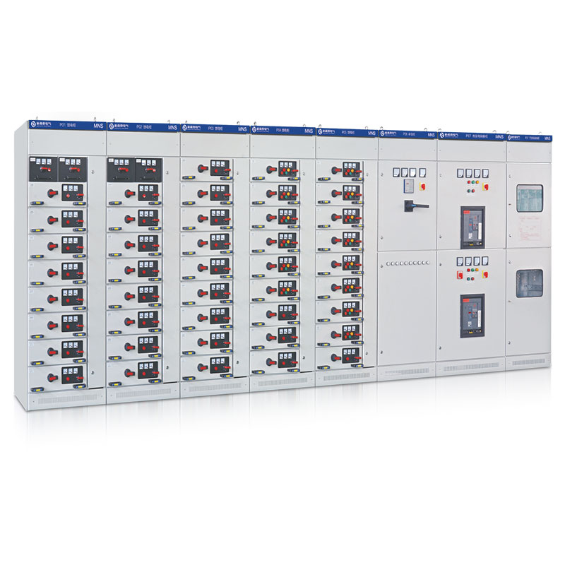
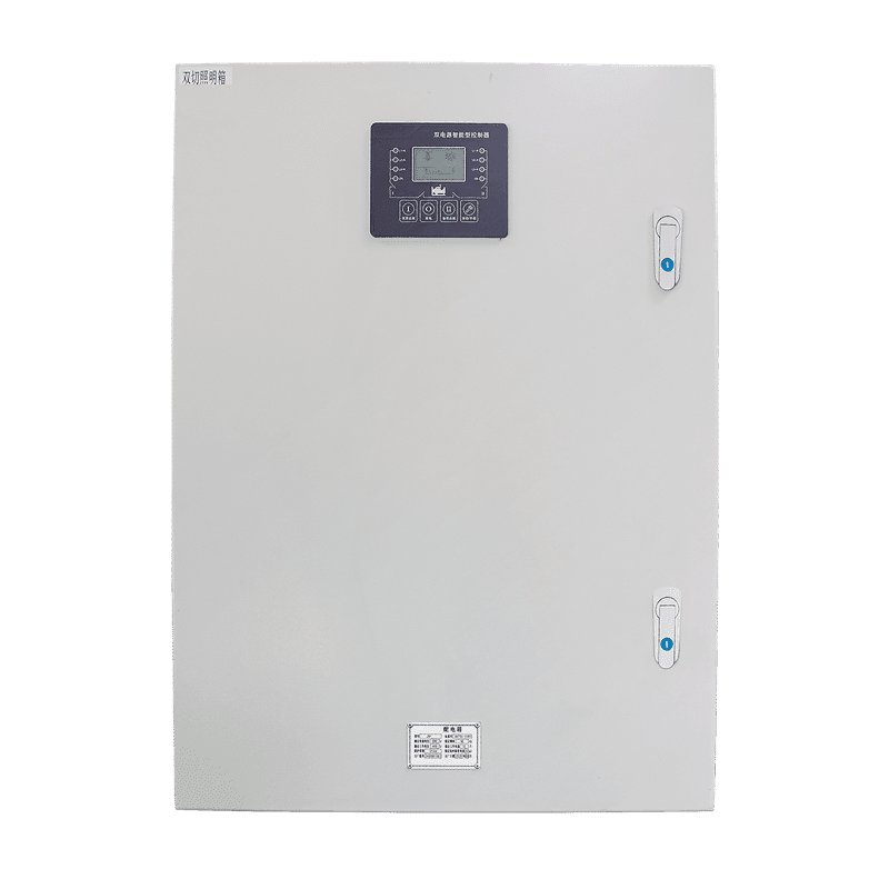
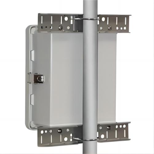
The machine control cabinet faces vibration, coolant mist, metal dust, and heat from drives — enclosure selection, gasket integrity, and thermal design follow the actual environment, not the catalog default. Layout separates power section (incoming, branch protection, drives) from control (PLC, safety, interface terminals) with disciplined segregation of signal classes; EMC practice — shield termination, filtered supplies, separation of power and signal routing — decides whether analog points stay trustworthy. Doors carry the HMI, pilot devices, and the safety devices their category requires. Panel documentation per market standard (UL 508A with NFPA 79 in North America; IEC 61439-1/-2 with IEC 60204-1 in IEC markets) completes the build; the panel-side specifics are covered in our PLC control panel applications guide.
Programming discipline and the operator interface
Machine programs succeed on structure: state-based sequencing rather than spaghetti logic, standardized function blocks for recurring machine elements, alarm text written for operators, and mode handling designed rather than accumulated. IEC 61131-3 provides the languages; project discipline provides the maintainability. The HMI layer — screens, permissions, and the tag/alarm strategy that feeds it — is engineered in parallel, as our HMI-PLC interface planning guide details. Networks to supervisory systems use industrial Ethernet or fieldbus per the plant standard, with failure behavior defined at every boundary: what stops, what holds last state, and what the operator sees.
Frequently asked questions
How much I/O margin should a machine panel carry?
10–20 percent spare per card type for machines with expected variants; channel capacity without spare terminals and terminal strip room buys nothing, so order the margin in terminal hardware too.
Standard PLC or safety PLC?
Depends on the safety functions: simple e-stop and guard monitoring can run on safety relays at moderate performance levels; integrated or numerous safety functions justify a safety PLC. The risk assessment decides — never the supplier’s current promotion.
What belongs in FAT for a machine control package?
I/O verification point by point against the list, sequence demonstration across all modes, safety-function validation with the agreed method, alarm display checks, and measured scan time. Simulation coverage must be stated — what was simulated, what could only be proven on the machine at SAT.
Who should own the PLC program source?
The end user, as a contract deliverable with passwords, back-ups, and the development project files — the alternative is permanent dependence on whoever wrote it.
How do machines with different vintages share one line control?
Gateway or wrapper approach: keep each machine’s native control, coordinate at a line PLC or supervisory layer over a defined protocol, and document the failure behavior at every gateway. The follow-up question to settle in design: which layer holds the sequence when one machine drops off the network — designed behavior versus discovered behavior is the difference between a recoverable fault and a full-line stoppage.
Procurement scenarios
For an OEM building its first PLC-controlled machine series, commission the full engineering package for machine one — narrative, I/O list, safety file, commented source code — and treat it as the template that machines two through twenty quote against; template reuse is where machine-builder automation becomes economical. For plants integrating one new machine into an existing line, order the interface engineering explicitly: protocol mapping, signal exchange list, and joint commissioning window with the line-control owner. For export machine packages, settle the destination market’s panel standard at order (UL 508A versus IEC 61439 path), and bundle the documentation language versions, safety validation file, and spare parts with the first shipment — retrofitting any of these after delivery routinely costs more weeks than building them in from the start.
ElectricalCabinet.net engineers machine control packages — panels, programs, and interfaces — as one scope; pair this guide with our PLC panel applications and programmable automation overview for the surrounding system.
 EN