










Factory automation control panels connect machines, sensors, actuators, drives, safety interfaces, and supervisory systems into an operating sequence. The correct panel depends on the production process, equipment interfaces, operating modes, environment, and documentation responsibilities — a generic automation panel image cannot establish the configuration required for another factory. This guide structures the planning inputs: the architecture layers, the interface list that feeds them, and the application patterns that recur across production lines.
This article explains the planning inputs for a factory-automation control panel. It does not replace the approved machine design, risk assessment, software specification, or project-specific electrical review.
What a factory automation panel coordinates
An automation panel may provide power distribution, PLC control, HMI interaction, drive interfaces, signal conditioning, networking, alarms, and connections to field devices. The exact boundary depends on the machine line and the systems supplied by other parties.
Start by describing:
- the production process and sequence of operations;
- machines, motors, valves, sensors, actuators, and instruments;
- normal, manual, automatic, setup, maintenance, and fault modes;
- operator controls, HMI screens, alarms, and acknowledgements; and
- interfaces to upstream, downstream, safety, and plant systems.
The PLC control cabinet page provides a product reference, while the project control narrative defines what the automation system must actually do.
Main architecture layers
Separate the panel design into layers so that missing responsibilities become visible.

| Layer | Planning questions |
|---|---|
| Power | Which supply, isolation, protection, and loads are included? |
| Control | Which PLC, relay, drive, or controller executes the sequence? |
| Instrumentation | Which sensors, feedback signals, and signal types are required? |
| Operator interface | What must operators start, stop, adjust, view, or acknowledge? |
| Communication | Which devices, networks, or plant systems exchange data? |
| Enclosure | What environment, access, mounting, and maintenance conditions apply? |
| Documentation | Which I/O lists, drawings, labels, manuals, and backups are required? |
The architecture should be reviewed against the real machine and process. Do not infer a PLC count, communication protocol, or I/O arrangement from a cabinet photograph.
Define the machine and field interfaces
Factory automation panels often sit between the control system and a large number of field devices. Create an interface list before selecting components or panel dimensions.
Record:
- device tag, function, location, and supplier;
- input or output type and expected signal behavior;
- motor, drive, valve, or actuator data;
- permissives, interlocks, alarms, and fault responses;
- cable routes, terminal responsibilities, and field wiring boundaries; and
- data exchanged with other controllers or supervisory systems.
This list supports the I/O schedule, terminal plan, software scope, and commissioning responsibilities. It is also the document that survives panel vendor changes — the interface list, not the part numbers, is what the next supplier inherits.
Application patterns
The same automation architecture can support different production processes, but the process logic and interfaces remain specific.
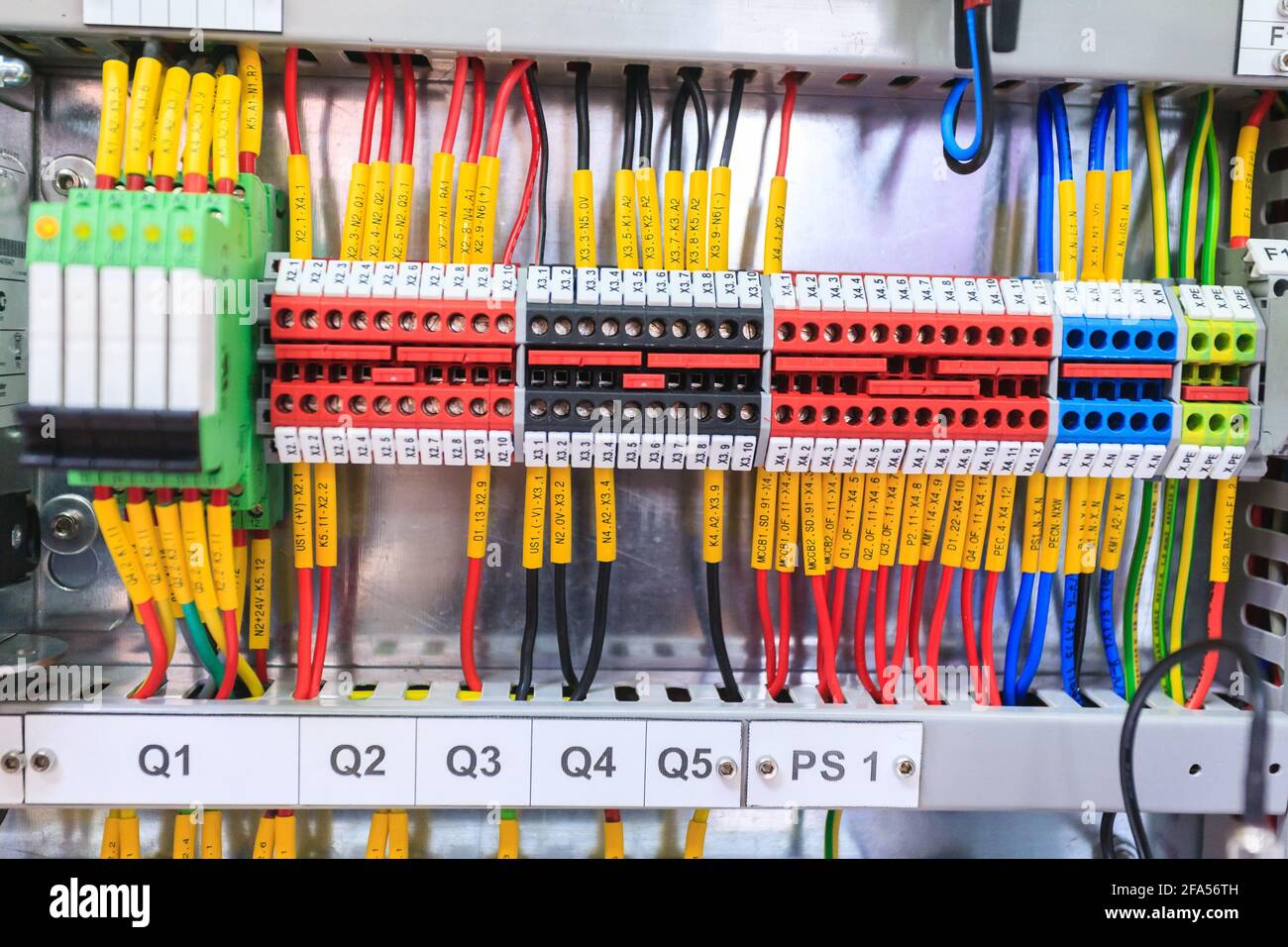
Machine or line coordination
A line-control panel may coordinate conveyors, machines, sensors, and interlocks. Define the sequence, handshakes, stop conditions, and restart behavior before describing the panel as a complete solution.
Drive-based motion or process control
Where motors require adjustable speed, define motor data, speed references, feedback, ramping, alarms, and local/remote modes. The VFD control panel design guide covers the drive-specific inputs.
Valve, fan, or process equipment control
Valve and fan applications require the process conditions, feedback, fail behavior, and maintenance modes to be documented. Images of PLC valve or fan cabinets are application illustrations, not proof of a customer delivery.
Monitoring and plant integration
If the panel exchanges data with SCADA, MES, or another plant system, define the data points, ownership, alarms, communication responsibility, and cybersecurity or access requirements that the project team has approved.
Standards relevant to factory automation panels
- UL 508A — the industrial control panel standard for the NEC market; automation panels shipped to North American plants are commonly built and documented under it, including the marked short-circuit current rating for the assembly.
- NFPA 79 — the electrical standard for industrial machinery in the NEC market, defining the machine-level wiring environment: disconnecting means, control circuits, conductor protection, and documentation practice around the panel.
- IEC 61439 — the assembly framework for panels delivered into IEC-market factories, defining rated values and the verification documents behind the nameplate.
- NEMA 250 / IEC 60529 — the enclosure protection references for the cabinet in its actual factory environment, from clean electrical rooms to dusty production floors.
Machine-safety and functional-safety requirements follow the machine risk assessment and its applicable standards — a separate engineering scope that the panel implements, not one it substitutes for.
Enclosure and maintenance requirements
The panel should be selected for the actual installation conditions and service plan. Review indoor/outdoor exposure, dust, moisture, heat, vibration, access, cable entry, door clearance, labels, spare capacity, and maintenance space.
If a NEMA or IP classification is requested, verify it for the exact model and configuration. A general factory-automation label does not prove a rating or certification. For the thermal dimension of that review, the enclosure temperature rise calculator estimates internal temperature from the heat load.
Documents and responsibility boundaries
Before quotation or design approval, identify the required deliverables and who owns each decision. Depending on the project, the package may include a control narrative, I/O list, general arrangement, schematic, terminal schedule, network diagram, label schedule, software scope, manuals, test records, and commissioning plan.
The project should state who supplies machine data, writes logic, installs field wiring, approves the electrical design, performs testing, and accepts the final system. This prevents a panel builder from being expected to infer process requirements from a component list.
Factory automation panel checklist
Confirm that the inquiry includes:
- process sequence and operating modes;
- equipment, load, sensor, and actuator list;
- I/O, alarm, permissive, and interlock information;
- HMI, PLC, drive, network, and plant interfaces;
- enclosure, environment, access, and maintenance requirements;
- required drawings, labels, manuals, and test records; and
- assumptions, exclusions, responsibilities, and open questions.
For component terminology, see the industrial control panel components guide. For design specification inputs, see the electrical control panel design specification guide.
Frequently asked questions
How early should the panel supplier be involved?
Before the I/O list freezes. A supplier reviewing the interface list while it can still change will flag spare-capacity, segregation, and thermal issues while they cost nothing; the same comments after design freeze cost schedule.
Follow-up: what if the machine design is still moving?
Then order the panel around the stable layers — enclosure, power architecture, terminal strategy — and gate the variable layer (device count, I/O cards) on the freeze date. Panels are rarely delayed by cabinets; they are delayed by decisions that arrive late.
Should automation panels be standardized across a factory?
Where the processes are similar, standardization pays in spares, training, and commissioning speed. Where processes differ genuinely, forced standardization produces panels that fit nothing well. Standardize the framework — terminals, labeling, documentation — before the hardware.
Who owns the network configuration?
The project should name one owner: addressing, segmentation, and cybersecurity boundaries drift into chaos when the panel builder, machine OEM, and IT each assume another is responsible. One named owner, documented at order time.
What spare capacity is normal?
An agreed percentage of spare I/O and terminal space — commonly ten to twenty percent — plus physical room in the enclosure. Undocumented spares are the cheapest thing to order and the most expensive to retrofit.
Final review
A factory automation control panel is successful when its power, control, field interfaces, operator functions, documentation, and maintenance requirements are defined together. Use industry labels to organize the conversation, but base the final configuration on verified process and equipment inputs.
Ordering scenarios
A production-line OEM commissioning a new line typically orders the master line panel first — the one holding the line-level sequence and plant interface — proves it through factory acceptance with the machine builders’ programs, then releases the station panels against the frozen interface list. The binding constraints are the interface freeze and the FAT date, because every station panel built early against a moving I/O list returns for rework.
A multinational building identical lines on two continents should place one pilot panel per regulatory regime: a UL 508A-built panel with NFPA 79-aligned documentation for the North American line, an IEC 61439-verified panel for the IEC-market line. The hardware converges over time; the documentation regimes never do, and the pilot pair keeps each line’s evidence trail native to its inspector.
 EN
EN