










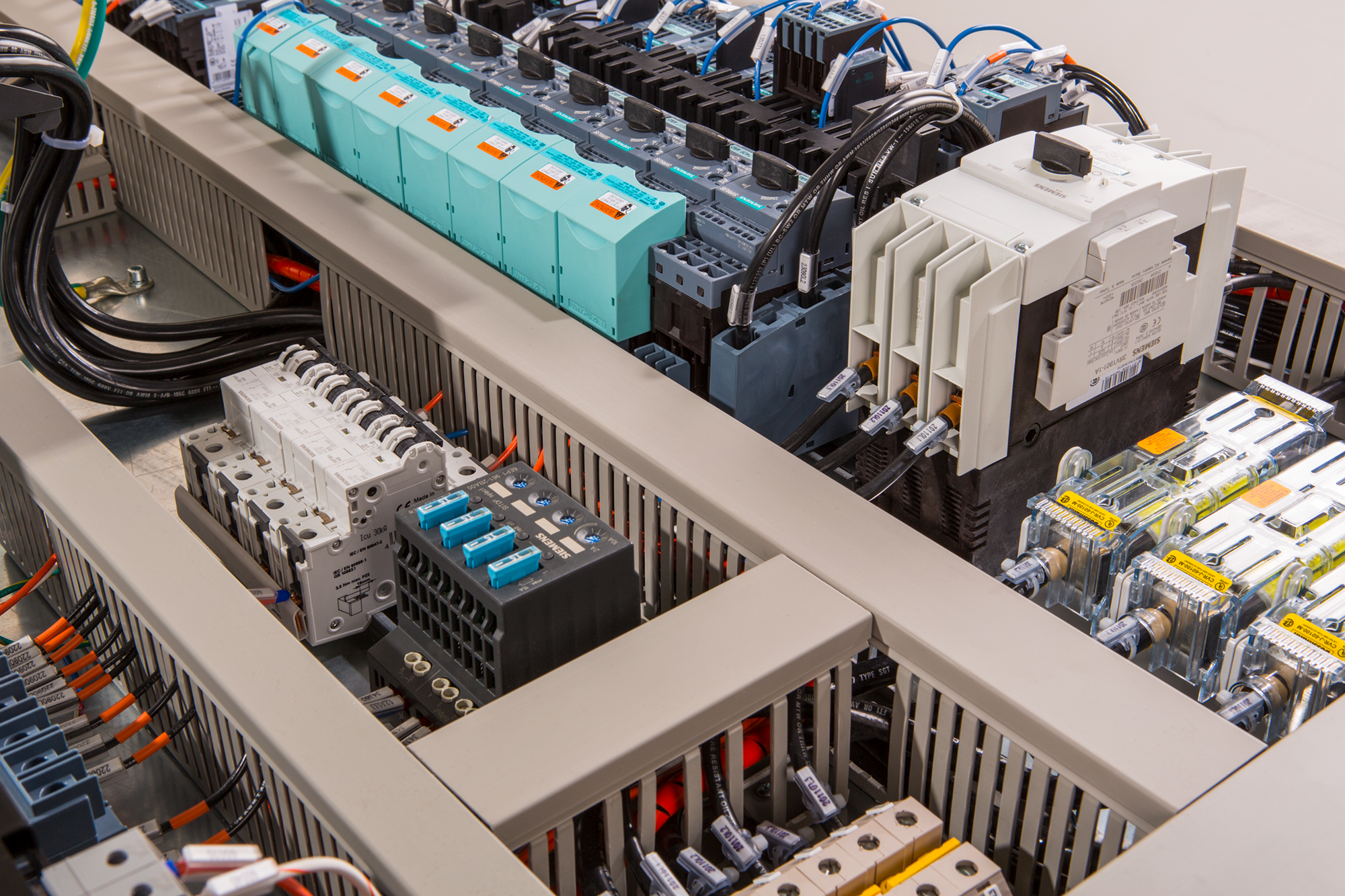
Motor control panels coordinate the starting, stopping, protection, monitoring, or speed control of motors and related equipment. The correct arrangement depends on the motor duty, operating sequence, control method, site conditions, and required interfaces — a panel name alone does not define the components, ratings, or commissioning scope. This guide explains the common arrangements, the power-versus-control responsibilities behind them, and the inputs that let a supplier quote the right panel instead of a generic one.
This guide is not a substitute for an approved electrical design or the documentation for the selected equipment.
What does a motor control panel do?
A motor control panel provides an organized point for power and control functions associated with one or more motors. Depending on the application, it may include disconnecting and protective devices, contactors or starters, overload protection, variable-frequency drives, PLC or relay logic, operator controls, alarms, and interfaces to field instruments or supervisory systems.
The actual arrangement should be selected from the process and motor data. A product image can illustrate a layout, but it cannot establish a suitable configuration for another project.
Common motor control panel types
Direct-on-line or starter panel
A starter arrangement is used when the motor process can operate with a defined starting and stopping method and the project requirements support that approach. The specification should identify the motor data, starting method, protection, control stations, interlocks, and feedback required.
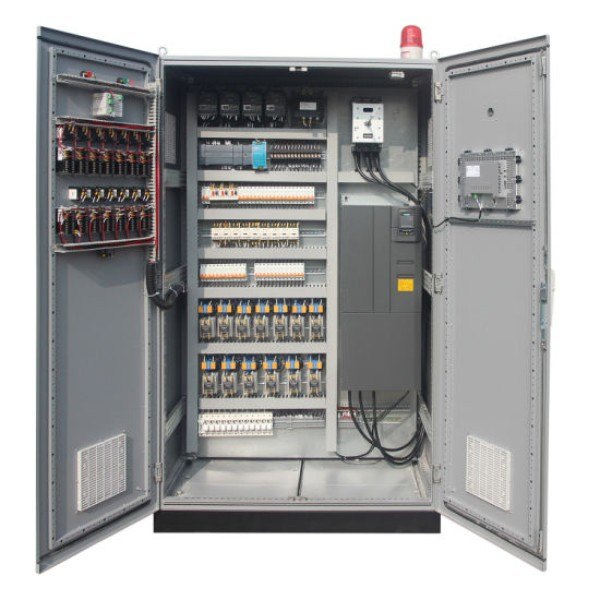
VFD motor control panel
A VFD arrangement is considered when the process requires adjustable speed, controlled acceleration or deceleration, or another drive-based operating objective. The inquiry should define the motor, operating range, feedback, control modes, alarms, and communication interfaces. See the VFD control panel design guide for the planning inputs.
PLC or automation motor control panel
An automation panel may coordinate motors with sensors, valves, sequences, alarms, and a supervisory system. The key inputs are the control narrative, I/O list, permissives, interlocks, local/remote modes, HMI requirements, and responsibility for programming and commissioning.
MCC or multi-motor arrangement
Where several motors and feeders must be organized as a coordinated system, an MCC or multi-motor arrangement may be considered. The final structure depends on feeder count, access, protection, isolation, monitoring, expansion, and the project’s electrical design. Do not treat “MCC” as a universal substitute for a project-specific lineup specification.
Pump or process-specific motor panel
Pump, fan, conveyor, and other process applications may require a dedicated control sequence, feedback, standby behavior, or alarm philosophy. These are application-specific configurations rather than interchangeable panel types. Review the pump control panel design guide when the motor control is part of a pumping process.
Panel types compared
| Type | Typical use | Key specification inputs |
|---|---|---|
| Starter panel | Fixed-speed motors with simple duty | Motor data, starting method, protection, stations |
| VFD panel | Adjustable speed, controlled ramps | Motor, range, feedback, thermal conditions |
| PLC automation panel | Sequenced, interlocked motor processes | Control narrative, I/O list, modes, HMI |
| MCC / multi-motor | Many motors as one coordinated system | Feeder count, isolation, expansion, access |
| Process-specific panel | Pumps, fans, conveyors with duty logic | Sequence, standby behavior, alarms |
Inputs to define before selecting a panel
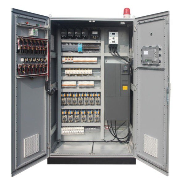
Collect the same core information for any motor-control arrangement:
- motor nameplate and supply information;
- load duty, operating range, and starting/stopping requirements;
- number of motors, lead/lag or standby behavior, and process sequence;
- local, remote, manual, automatic, and maintenance modes;
- sensors, feedback, alarms, permissives, and interlocks;
- PLC, HMI, SCADA, drive, or communication interfaces;
- installation environment, mounting, access, and cable entry; and
- required drawings, schedules, manuals, inspection records, and commissioning boundaries.
Without these inputs, a supplier cannot reliably determine the required component arrangement or documentation package.
Power and control responsibilities
Separate the power path from the control and interface requirements during design review.
| Area | Questions to define |
|---|---|
| Incoming power | What supply, isolation, protection, and termination information applies? |
| Motor circuit | Which motor or load is controlled, and what duty data is available? |
| Control logic | Which sequences, permissives, alarms, and interlocks are required? |
| Operator interface | What must be started, stopped, displayed, acknowledged, or adjusted? |
| External interfaces | Which instruments, PLCs, drives, or supervisory systems connect? |
| Enclosure | Where is the equipment installed, and what environment and access apply? |
| Documentation | Which drawings, labels, manuals, and inspection records are required? |
This separation makes responsibility gaps visible before fabrication. It also prevents the panel builder from being expected to infer process logic from a motor list alone.
Standards relevant to motor control panels
- UL 508A — the industrial control panel standard for the NEC market, governing how motor-control components combine into a listed panel, including the marked short-circuit current rating.
- NFPA 79 — the electrical standard for industrial machinery in the NEC market, defining the machine-level wiring rules around the panel: disconnecting means, control circuits, and conductor protection.
- IEC 61439 — the IEC assembly framework for motor-control assemblies in IEC-market projects, defining the rated values and verification behind the panel’s nameplate.
- IEEE C37 — where the motor-control arrangement interfaces with metal-enclosed switchgear upstream, the equipment ratings at that boundary reference this North American standards family.
- NEMA 250 / IEC 60529 — the enclosure protection references for the cabinet in its environment.
Motor and starter component standards themselves are product-level documents; the panel’s responsibility is to select and coordinate devices per the project design and to evidence the assembly rating, not to restate component test procedures.
Common selection mistakes
- Choosing a starter, VFD, or MCC arrangement before defining the process duty.
- Assuming every motor-control panel requires a PLC or HMI.
- Treating a generic enclosure image as proof of a rating, component list, or certification.
- Omitting remote commands, feedback, permissives, or fault behavior from the inquiry.
- Describing a motor-control photograph as a customer project without project evidence.
- Using a standard name without defining the documents and responsibility boundaries.
A quotation checklist
Before requesting a motor control panel quotation, provide the motor and load list, operating sequence, control modes, I/O and interface requirements, installation conditions, enclosure expectations, and required documentation. Ask the supplier to identify assumptions, exclusions, and configuration-dependent values.
For component terminology, see the industrial control panel components guide. For variable-speed pump applications, see the VFD pump control panel selection guide. For the thermal dimension of enclosure selection, the enclosure temperature rise calculator estimates internal temperature from the heat load.
Frequently asked questions
When does a motor need a VFD instead of a starter?
When the process needs adjustable speed, controlled acceleration, or energy management across varying demand — and the supply and motor support drive operation. Fixed-duty motors at constant speed are served correctly and economically by starters.
Follow-up: can a starter panel be converted to VFD later?
Sometimes by adding a drive where space, cooling, and the motor allow, but the enclosure, thermal design, and control wiring were built for the original arrangement. Where drive conversion is foreseeable, order the enclosure and terminals ready for it.
Is an MCC always the answer for many motors?
No — a multi-motor panel or grouped panels may serve modest counts better. MCC-style construction earns its cost where feeder count, withdrawal or isolation requirements, and expansion plans justify the structure. The electrical design decides the architecture.
Do motor panels include overload protection?
Motor protection is inherent to the arrangement — but which devices provide it, and how they are set, follows the motor data and applicable requirements. The inquiry should include the motor list precisely so protection is coordinated, not assumed.
Who sets the protection parameters?
The project electrical design, from the motor data and coordination study. The panel builder implements the specified devices and settings; unspecified values are a question back to the engineer, not a default guess.
Final review
The best motor control panel type is the one that matches the actual process, motor data, control interfaces, environment, and documentation requirements. Use the type names to organize the discussion, but make the final selection from verified project inputs rather than from a generic label.
Ordering scenarios
A plant maintenance team replacing aging motor panels typically orders the highest-duty panel first — often the largest motor group — proves its protection settings and starting behavior against the real load, then releases the smaller panels against the proven pattern. The binding constraints here are the protection study sign-off and motor data completeness, because settings built on assumed motor data fail the first real overload test.
An OEM building machine lines for both NEC- and IEC-referenced markets should fix the build regime per destination at the first order: UL 508A construction with NFPA 79-aligned machine documentation for the North American machines, IEC 61439 assembly verification for the others. The motor lists may be identical; the evidence packages are not, and a mixed run shipped with one package serves neither inspector.
 EN
EN