

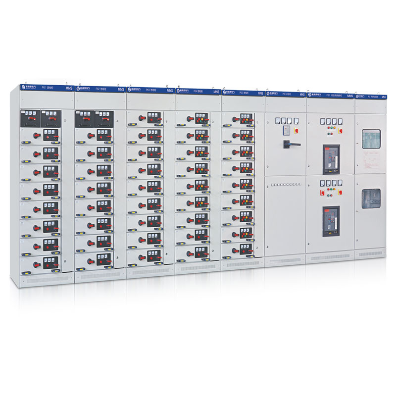


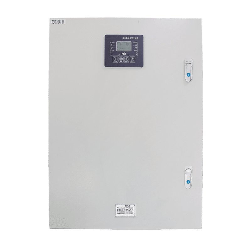


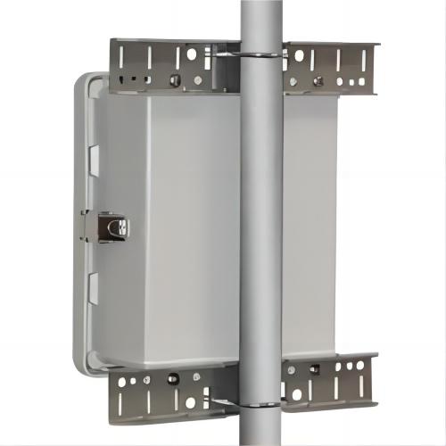


Basically, Switchgear Safety is crucial to every building power system. Electrical switchgear makes up part of each electrical distribution system, which assures the safe and efficient running of electrical circuits. The importance of the devices is to control and isolate electricity flow to protective equipment and preclude fault currents that can result in dangerous situations or very expensive downtimes. While switchgear has been designed with durability and reliability in mind, it doesn’t last forever. Proper care, maintenance, and consideration can allow extending the life of a switchgear manifold far beyond what even the manufacturer can expect thereof. In this paper, we discuss key best practices and proactive strategies that can be implemented to maximize the life of your switchgear, which could even double the rated service life expected. Whether you deal with a small commercial setup or a large industrial facility, these tips will ensure that your switchgear keeps functioning at its best and thus serves you both in Switchgear Safety and reliability for many years.
What is Switchgear?
Switchgear is a generic term applied to all types of electrical apparatus used to control, protect, and isolate electrical equipment forming part of a power distribution network. The devices ensure the safety and reliability of the electrical system; hence, their use has increased much in industry and commerce. These devices that make up this switchgear include switches, circuit breakers, fuses, disconnect switches, grounding equipment, and surge protection devices—each of them has some form of function in management regarding electrical power.

Switches and circuit breakers permit gaining control over the flow of electricity, therefore allowing the operator to connect safely or disconnect electrical circuits when required. Fuses and surge-protective devices prevent electrical overloads and transient voltage spikes from damaging equipment, hence improving system stability. Disconnects and grounding equipment also ensure that circuits can be safely isolated for maintenance or upon fault conditions.
These components are normally housed in a grounded metal enclosure, not only for mechanical protection but also to avoid shock and fire hazards. Metal enclosure will further protect the switchgear from environmental impacts such as dust, moisture, and temperature variations that add more to its strength and reliability. However, sometimes, like in substations and distribution systems outdoors, the switchgear is installed outdoors. Such aspects would have ancillary considerations that need to be accounted for in this switchgear functionality extension with regard to parameters such as weatherproofing or environmental protection.
It can be as small as a commercial building or even as huge as industrial complexes and utility substations. Switchgear enables the safe distribution and management of electrical power by allowing the flow of electricity where needed, while at the same time protecting the equipment and the people from potential hazards.
Understanding Switchgear Safety and Life Expectancy
Switchgear has an age-dependent average of its manufacturer, mainly determining factors such as the voltage, environment of operation, patterns of usage, and quality of maintenance, among others. In general, low-voltage switchgear has a standard lifespan of 20 to 30 years, and high voltage might exceed 40 years. All of these are rough averages, as the actual life of the switchgear can vary tremendously by how well it is maintained or the conditions under which it operates.

For instance, switchgear that is clean and installed in a controlled environment, where temperatures and relative humidity are usually constant, will have a longer life expectancy compared to that which is exposed to harsh surroundings such as high or low temperature, dust, moisture, or corrosive elements. By the same token, switchgear that is serviced at high regular loads or rather at heavy-duty cycles might wear quickly, which might render it short-lived.
Regular maintenance is an essential contributor to extending the life of the switchgear. In the course of routine inspections, attending to the replacement of worn or damaged components in a timely manner and proper lubrication of moving parts, the chances of equipment failure can decrease. Predictive maintenance usually involves monitoring temperature, vibration, and other operational parameters in ways that will alert impending failures to proactively prevent failure mechanisms that will further enhance the life of the switchgear.
The design and manufacturing quality of switchgear matters, in an ultimate manner, towards its life expectancy, but how it is used and maintained is, therefore, a key variable. Knowledge of the best practices in the operation and maintenance of the switchgear could ensure an extension of its lifespan way well beyond the average, thus assurance of effective and reliable performance but without incurring the high costs that would accrue from new acquisitions.
Key Practices to Extend Switchgear Safety and Life Expectancy
Establish a Regular Maintenance Schedule
Switchgear requires its apparatus to be subjected to consistent maintenance in order to prolong its life. Maintenance, planned at different periods by a chartered electrical engineer, will ensure that all tasks are carried out with time for Switchgear Safety. The program needs to include preventive measures—cleaning and inspections—with corrective actions involving repair and replacement of parts.
Tip: Put a system process in place to formalize this by using a work order system that automatically generates tasks on a frequency basis so nothing falls through the cracks.

Monitor Temperature to Prevent Thermal Damage and Switchgear Safety Risks
The main factor responsible for reducing the useful life of switchgear equipment and risking Switchgear Safety is overheating. The majority of electrical defects, as well as the sources of overheating in the operating environment, can cause heat damage. Normal thermal monitoring through the use of infrared thermometers or thermal imaging cameras should be able to pick up the relevant hot spots that might mean a problem.
Action: Check areas where the heat reading is abnormal; do something to prevent overheating, like increasing ventilation or installing cooling.
Conduct General Monitoring and Visual Inspections for Switchgear Safety
This shall be complemented, together with temperature monitoring, by visual examination. Check for physical damage, like broken insulation or loose connections, and observe any unusual sound or vibration that may be indicative of its underlying conditions.
Preventive Measure: The problems identified during the visual examination should be attended to promptly to prevent them from developing into major ones that shorten the life span of the switchgear.
Implement Arc Flash Protection Measures for Switchgear Safety
Arc flash incidents can cause extensive damage to switchgear, which includes contact wear, insulation breakdown, and, at worst, fires or explosions. Put in fast-acting breakers and other switches that are able to clear an arc fault quickly. Further, detection of arc flashes can be done with the help of the light sensors incorporated in the design of new monitoring systems.
Safety Tip: Properly label all electrical panels and cabinets in order to prevent unauthorized/unqualified personnel from working with the equipment.
Consider Retrofitting with Modern Technology for More Switchgear Safety
Older switchgear may sometimes not function effectively or, worse still, become unsafe with advancing technology. Retrofitting it with new components at strategic intervals shall make it perform better and help in the extension of life. This shall include flash mitigation devices and state-of-the-art monitoring systems.
Upgrade Strategy: As a part of retrofitting, make sure that the repairs are done on time to rectify the problems before they cause long-term damage.

Switchgear Maintenance Schedule: What to Inspect and How Often
Effective switchgear maintenance follows a tiered schedule: the more frequent the interval, the simpler the task. Industry practice is anchored by the ANSI/NETA Standard for Maintenance Testing Specifications (MTS) for Electrical Power Equipment and Systems, which publishes recommended inspection and test intervals together with acceptance values, and by IEEE C37.20.1, the standard for metal-enclosed low-voltage switchgear, around which industry maintenance guidance for this equipment class is built. The schedule below is a widely accepted baseline for a typical indoor electrical switchgear installation; hot, dusty, damp, or high-duty-cycle environments should compress these intervals, and the manufacturer’s instructions always take precedence.
| Interval | Focus | Typical Activities |
|---|---|---|
| Weekly to monthly (energized walkthrough) | Visual condition and thermal behavior | Look for discoloration, burnt odors, unusual noise, tracking marks, condensation, and tripped indicator flags; verify space heaters and ventilation; scan accessible connections and bus joints with an infrared camera under normal load. A common field guideline is to investigate any point running roughly 10 °C (18 °F) or more hotter than a comparable phase connection. |
| Monthly to quarterly | Environment and housekeeping | Clean or replace ventilation filters; confirm anti-condensation heaters operate; check door seals, gaskets, and water ingress paths; record load currents and compare them against nameplate ratings to catch sustained overloading early. |
| Annual (planned outage) | Electrical testing and mechanism care | Insulation resistance testing with a megohmmeter on de-energized sections; contact and arc-chute inspection on withdrawn breakers; connection torque checks against manufacturer values; lubrication of operating and racking mechanisms with the specified grease; exercising seldom-operated breakers; protective relay and trip-function verification. |
| Every 3 to 5 years | Major inspection and diagnostics | Comprehensive overhaul and cleaning; partial discharge testing (online or offline) on medium-voltage equipment; primary or secondary injection testing to verify breaker long-time, short-time, and instantaneous time-delay characteristics; ground-fault and interlock testing; detailed bus inspection with re-insulation of aged barriers and supports. |
Two points deserve emphasis. First, infrared thermography only tells the truth under real load: schedule the survey while the equipment is carrying normal operating current, because a lightly loaded connection can hide a serious defect. Second, breakers that rarely operate age differently from those that operate daily—their lubricant settles and mechanism friction grows—so even standby or seldom-used breakers should be exercised and tested on the annual cycle. NFPA 70B, which became a mandatory standard for electrical equipment maintenance programs in its 2023 edition, is a useful companion reference when formalizing these intervals into a documented, auditable plan.
Equally important is what happens to the data. Inspection findings, infrared temperatures, insulation resistance readings, and breaker test results are only useful when they are recorded against the same equipment over time, because most aging signatures appear as slow trends rather than sudden changes. A computerized maintenance management system (CMMS) or even a well-kept spreadsheet lets the team compare this year’s megohm values against last year’s, flag a connection that runs a little hotter every quarter, and justify a retrofit with evidence instead of intuition. The ANSI/NETA MTS tables are designed for exactly this kind of comparison, since they define both the test methods and the acceptance values against which each result should be judged.
Safety Standards and Compliance: NFPA 70E, OSHA, and IEEE
Maintaining switchgear safely means working inside an overlapping framework of US, Canadian, and IEEE standards. Knowing which document requires what keeps an inspection program both legally compliant and genuinely protective. The five most frequently cited references are summarized below.
- NFPA 70E, Standard for Electrical Safety in the Workplace. It requires an arc flash risk assessment before energized work, defined approach boundaries (limited approach, restricted approach, and the arc flash boundary), either an incident energy analysis or the use of its PPE category tables, energized work permits, and documented training for anyone exposed to electrical hazards. In practice, this is why arc flash warning labels belong on every switchgear lineup.
- OSHA 29 CFR 1910.303. It requires electrical equipment to be installed and used according to its listing, to be free from recognized hazards, and to have sufficient working space and clearances around energized parts so the equipment can be safely examined, adjusted, serviced, and maintained.
- OSHA 29 CFR 1910.335. It requires employees working where electrical hazards exist to use protective equipment appropriate to the hazard—voltage-rated gloves, insulated tools, arc-rated clothing—and to use alerting techniques such as signs, barriers, and attendants to warn and protect other workers.
- IEEE C37.20.7. It defines the test procedure that verifies arc-resistant switchgear: a controlled internal arc is initiated, and the enclosure must channel hot gases and arc by-products away from the operator. Type 1 construction protects only at the front of the equipment; Type 2 protects the front, sides, and rear—so the rating only helps where personnel actually stand.
- CSA Z462 (Canada). The Canadian workplace electrical safety standard, harmonized in most technical content with NFPA 70E; it carries the same arc flash risk assessment, boundary, and PPE obligations for Canadian facilities and cross-border operations.
Compliance is not a one-time labeling exercise. Incident energy changes whenever protective device settings, available fault current, or utility contributions change, so the arc flash analysis and the resulting equipment labels should be reviewed whenever those inputs change and at least as often as your site’s safety program defines. Pairing the documentation side of these standards—labels, permits, and training records—with the physical maintenance schedule above is what turns written requirements into day-to-day practice.
Two practical compliance habits close the loop. First, training: NFPA 70E and CSA Z462 both tie worker qualification to documented, recurring training plus field-specific energized work procedures, not to a one-time orientation. Second, periodic audits: a yearly walkdown that verifies labels are legible, boundary distances are current, PPE is within its service life, and lockout devices are actually available will catch the small gaps that inspections of the equipment itself never reveal.
Switchgear Life Extension: Retrofit or Replace?
Even the best maintenance program only slows aging; it cannot stop it. At some point every facility faces the same question: when to replace switchgear, and when a targeted retrofit will buy another decade of safe service at a fraction of the cost. Making that call well starts with understanding what actually fails as switchgear ages.
How Switchgear Ages
- Insulation degradation. Thermal cycling and sustained operation at elevated temperature gradually embrittle solid insulation, while partial discharge activity slowly erodes epoxy bus supports and primary insulation. Once insulation strength falls below test thresholds, failure risk rises steeply rather than linearly.
- Contact erosion. Every fault interruption vaporizes a small amount of contact material. After decades of operations and fault clearings, contact surfaces roughen, contact resistance climbs, and the resulting localized heating accelerates insulation damage around the interrupter.
- Lubrication breakdown. Grease in operating and racking mechanisms hardens, dries out, or migrates away from the surfaces it was meant to protect. Higher mechanism friction slows breaker travel—and a slower breaker clears faults later, which raises the arc flash incident energy during an event.
- Bus connection oxidation. Oxide films grow at bolted bus joints, raising contact resistance and creating hot spots that feed on themselves: more heat generates more oxidation, which generates more resistance and still more heat.
Retrofit Options That Extend Service Life
When the enclosure, bus structure, and insulating system are fundamentally sound, several proven retrofit paths can defer replacement by ten years or more.
- Breaker retrofit and racking upgrades. Direct-replacement retrofit breakers engineered for legacy cells can replace obsolete air or magnetic-air breakers, restoring interrupting capability and a dependable spares supply without replacing the entire lineup; worn racking mechanisms and interlocks are refurbished at the same time.
- Protection relay modernization. Replacing electromechanical relays with digital protection removes drift-prone discs and springs in favor of accurate, self-monitoring time curves, event records, and remote communication. Because faster, more precise tripping shortens fault clearing time, this upgrade directly lowers arc flash incident energy as well.
- Bus refurbishment. Cleaning bus runs, replacing aged insulation barriers and supports, re-torquing joints to specification, and verifying bracing restores thermal performance and short-circuit withstand without a full teardown.
- Condition monitoring retrofit. Continuous thermal monitoring and partial discharge sensors convert the calendar-based maintenance schedule above into a condition-based one, catching degradation months before it becomes a failure.
When to Replace Switchgear Instead
Retrofit is not always the answer. Replacement is usually the better decision when the original manufacturer has declared the platform obsolete and spare parts are scarce or unobtainable; when insulation resistance or partial discharge results trend worse across consecutive test cycles; when the equipment has suffered repeated major failures; or when a retrofit quotation approaches a large share—commonly quoted at around half or more—of the cost of a new installation. Load growth beyond the existing rating, or an arc flash study that cannot reach acceptable energy levels even after protection upgrades, points the same way. A new lineup also brings arc-resistant construction tested to IEEE C37.20.7, integrated monitoring, more efficient designs, and modern interrupting technology.
A simple decision frame keeps the discussion honest: if the enclosure and bus structure are healthy, the platform is still supported, and the retrofit addresses a specific weakness—contacts, relays, or monitoring—retrofit usually wins on cost and downtime. If the weakness is the insulation system itself, the platform is orphaned, or the arc flash study cannot be satisfied any other way, replacement wins on risk. Document the reasoning either way, because the next engineer who inherits the lineup will need it.
Finally, make this decision early. New switchgear lead times have stretched dramatically in recent years—commonly many months, and in some market conditions well beyond a year—so a facility that waits until the equipment is visibly failing may face an unavoidable gap between what it needs and what it can get. A practical approach is to evaluate the retrofit-versus-replace question two to three years before the end of the targeted service life, leaving time for engineering studies, procurement lead time, and a planned outage window.
Conclusion
These Switchgear Safety best practices can do much to extend life expectancy. Be guided on the principal issues for making sure that your switchgear keeps on being reliable and effective: frequent maintenance, thorough monitoring, and timely upgrading. With a proactive approach, you will assure maximum return from your investment by reducing the need for costly replacements and minimizing electrical system downtime. Feel free to contact us for help.
 EN