










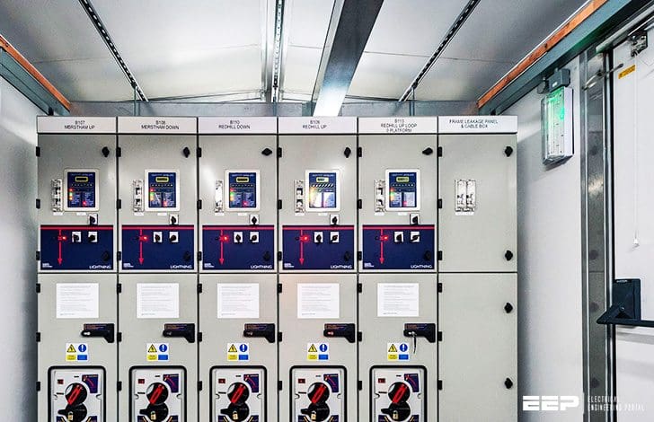
A correct gas-insulated switchgear installation procedure runs through seven gates: site readiness, equipment receipt and handling, mechanical assembly, primary and secondary connections, grounding, gas and electrical testing, and documented handover. Skipping any gate — most commonly the receipt inspection and the pre-energization test record — is what turns a factory-tested GIS lineup into a commissioning problem. This guide walks each stage with the checks that matter, the evidence to collect, and the safety boundaries to enforce, so installation proceeds against a checklist rather than memory. Final ratings, code compliance, safety procedures, and testing requirements must be confirmed by qualified engineering for the actual project.
Stage 1: Site readiness before the equipment ships
Confirm the switchgear room is complete and dry before delivery: civil works finished, doors and cable entries cut to the drawings, ventilation or air conditioning running, permanent or temporary power for tools and testing available, and the room clean of construction dust. GIS tanks are sealed, but secondary compartments, relays, and cable plugs are not; construction-phase moisture and cement dust are leading causes of insulation test failures at commissioning. Check access paths — door widths, corridor corners, hoisting points, and floor loading — against the transport weights in the manufacturer’s drawings, and agree the delivery sequence so panels arrive in erection order.
Stage 2: Receipt, storage, and handling
At unloading, inspect transport recorders if fitted, examine tanks for impact marks, verify gas density monitor readings against the factory record, and photograph any anomaly before signing delivery documents. Store panels indoors, upright, in stable temperature; unavoidable outdoor storage follows the manufacturer’s covering and inspection instructions with recorded weekly checks. Move panels only with the specified lifting points and transport bolts; a dropped or jolted tank can pass visual inspection yet fail gas tightness or internal alignment later.
Stage 3: Erection and mechanical assembly
Set the first panel against a marked datum, level it with the adjustable base fittings, then build the lineup panel by panel, aligning busbar coupling flanges to the tolerances in the erection manual. Bolt rated torque values and record them. Where panels join across gas zones, fit new sealing gaskets — never reuse them — and follow the bolt sequence given for gas-flange joints. Complete cable support steel, extension frames, and roof or shroud sections, then re-check lineup straightness before any primary connection is made.
Define the system boundary at every stage
Separate equipment, cabinet, field devices, power, protection, networks, installer scope, commissioning, and maintenance responsibility before installation starts, and keep the boundary visible in the site minutes. The inputs below should be documented and kept current; they are the same inputs that governed procurement, now reused to govern installation.
| Input | Why it matters during installation |
|---|---|
| Equipment and operating data | Loads, feeders, I/O, sequences, switching duty, environmental conditions, and operating modes define what “installed correctly” means. |
| Cabinet and installation | Layout, compartments, heat, cable entry, clearances, access, labels, grounding, and service sequence drive the physical checks. |
| Evidence and testing | Drawings, BOM, settings, inspection points, FAT/SAT scope, test records, manuals, and open decisions become the handover file. |
| Supplier responsibility | Interfaces, exclusions, assumptions, documentation ownership, training, spares, and qualified review decide who signs each hold point. |

Stage 4: Primary, secondary, and grounding connections
Make cable terminations with the plug types and torque values specified for each rating, using calibrated torque wrenches. Complete secondary wiring between panels and to the marshaling cabinet against the terminal schedules, and implement the grounding scheme exactly: tank-to-tank bonding straps, the main earth bar connection, and any required neutral earthing. Grounding is inspected before any test voltage is applied — both for test validity and for safety.
Stage 5: Gas system checks
For SF6 or alternative-gas compartments, verify density monitor alarm and lockout settings against the nameplate, record pre-energization pressure and temperature, and, where the erection manual requires, perform a gas dryness or micro-water check on compartments opened during transport or assembly. Any compartment that lost pressure in transit must be leak-located and re-filled by trained personnel with proper gas handling equipment — SF6 handling is regulated in many jurisdictions, and venting is prohibited.
Stage 6: Pre-energization electrical testing
The routine test set performed in the factory is repeated or verified on site: circuit resistance of main current paths, power-frequency withstand on primary insulation at the reduced site-test level stated by the standard, secondary injection checks on protection relays, function tests of interlocks (circuit-breaker, disconnector, earthing switch sequencing), and verification of alarm and trip routing to the RTU or SCADA where in scope. Record instrument serial numbers and calibration dates — commissioning reports without calibration traceability are routinely rejected by utilities.
| Test | What it verifies | Typical acceptance logic |
|---|---|---|
| Main circuit resistance | Joint quality across panel couplings and cable lugs | Compare with factory values; investigate deviations beyond the manual’s tolerance |
| Power-frequency withstand | Primary insulation integrity after transport and site work | Site test voltage per IEC 62271-200 routine-test provisions, applied phase-to-earth with other phases earthed |
| Secondary injection | Relay settings, trip paths, and breaker operation | All stated settings injected; trip times within relay data |
| Interlock function | Safe switching sequence | Every prohibited operation physically blocked; every permitted operation succeeds |
| Gas density alarms | Sealing system health | Alarm and lockout thresholds match nameplate; no unexplained drift over the observation period |
Safety boundaries during installation and commissioning
Enforce a written switching and isolation regime: points of isolation, earthing applied before work, keys held in a lockout system, and live-tank work prohibited. Treat gas compartments as pressure vessels — never loosen flange bolts on a pressurized unit. Where internal arc classification relies on pressure relief channels, confirm the relief direction and relief ducts (if fitted) before energization, and keep the arc-energy relief zones clear of routine access paths.
Standards referenced during GIS installation
IEC 62271-200 defines the routine and type-test framework whose site verification mirrors factory practice, including internal arc classification and the meaning of the ratings on the nameplate. IEC 62271-100 applies to circuit-breaker checks, and IEC 61936 (or the local earthing and installation code such as NEC Article 250 contexts in North America) governs system earthing and installation clearances. SF6 gas handling falls under environmental regulation — in the EU, the F-Gas Regulation (EU) 2024/573 restricts emissions and mandates qualified personnel and record keeping, with SF6 phase-out stages for new MV switchgear beginning 2026 for ratings up to 24 kV. For the component-level and regulatory background, see the gas insulated switchgear guide.
Frequently asked questions
How long does GIS installation take compared with air-insulated switchgear?
Lineup assembly is usually faster — sealed units arrive factory-aligned and gas-checked, so site work concentrates on bolting, cabling, and testing. A typical MV room of 6–10 panels moves from delivery to energization in one to three weeks when the room is ready and panels arrive in sequence.
Can we install GIS in a room still under construction?
Only with dust and moisture control, temporary climate control, and a signed deviation from the manufacturer. Construction dust in secondary compartments and humidity in cable plugs are the two most common causes of failed withstand tests.
What happens if a gas compartment shows low pressure at delivery?
Do not energize. Photograph the density monitor, record temperature, notify the manufacturer, and have the compartment leak-tested and re-filled by qualified gas personnel — the leak cause must be found and closed, not just topped up.
Which site tests can be skipped if the factory FAT was witnessed?
None automatically. Factory tests verify the unit before shipment; site tests verify it after transport and site assembly. Even fully witnessed FAT is followed by at least circuit resistance, interlock, and secondary functional checks on site, and by withstand tests where site work touched primary connections — follow-up question to settle with the manufacturer: which site-test voltage applies after a partial re-assembly, since that value depends on what was opened.
Who signs the handover?
The installer, the commissioning engineer, and the owner’s representative, against the agreed SAT scope. Each holds signed test records, calibration references, gas records, as-built drawings, and a punch list with owners and dates for every open item.
Two realistic installation scenarios
For an export project shipping 8 panels to a site with a 10-week window, sequence the order as follows: first deliver two panels with the commissioning engineer’s toolkit, spares, and gas-filling equipment; erect, test, and energize the first bay while the balance ships. This staged approach surfaces interface issues early but only works when the manufacturer agrees to split delivery at the order stage — confirm this before contract, not after. For a retrofit inside an operating substation under IEC-market rules, plan isolation windows around the tests that require de-energizing adjacent boards, and specify a temporary bypass or mobile unit only if the load study justifies it; in NEC markets, additionally confirm that site test levels and grounding documentation satisfy the local inspection authority before energization is requested.
ElectricalCabinet.net manufactures medium voltage switchgear and can scope supply so that installation stages, test records, and handover documentation match your project plan from the first drawing review.
 EN
EN