










A grounding transformer provides an artificial neutral point — and with it a defined path for zero-sequence (earth-fault) current — on a three-phase system that has none, most commonly an ungrounded or delta-connected MV network. Connected in zigzag or wye-delta, it lets the system be earthed through a resistor or reactor, which limits earth-fault current to a chosen value, makes faults detectable by protection, and controls transient overvoltages. Its working principle, its ratings, and its protection interfaces are what this guide explains — because a grounding transformer is not selected like an ordinary power transformer: it carries little load in normal operation and is rated for short-time fault duty instead. A generic grounding-transformer description cannot establish a safe fault-current value; those decisions require a qualified power-system study and project-specific engineering.
Why a grounding transformer is used
A grounding transformer can provide a neutral point or a defined path for zero-sequence current in a system that otherwise lacks a suitable neutral. It may support system grounding, fault detection, and coordination with protection equipment. The connection and grounding method must be selected as part of the complete power-system design: the fault-current value chosen sets the resistor, the transformer’s short-time rating, and the protection sensitivity together.
Working principle: how zero-sequence current finds a path
On a delta or ungrounded-wye system, an earth fault on one phase leaves zero-sequence current with nowhere to flow — the system’s neutral floats, fault current is only capacitive charging current, and transient overvoltages stress insulation. A grounding transformer changes that geometry. In the zigzag (interconnected-star) connection, each phase winding splits into two halves on different limbs, wound so that positive- and negative-sequence fluxes cancel — the transformer presents high impedance to normal load currents — while zero-sequence fluxes add, presenting a low-impedance path for earth-fault current through the neutral point. In the wye-delta arrangement, the wye connects to the system with its neutral earthed (usually through a resistor), and the delta circulates the zero-sequence current internally. In both constructions, normal three-phase power flows barely engage the unit; it exists for fault conditions, and its rating basis reflects that.
Zigzag versus wye-delta
| Attribute | Zigzag (interconnected star) | Wye-delta (star-delta) |
|---|---|---|
| Neutral provision | Directly provides the neutral point | Neutral from the wye winding |
| Zero-sequence behavior | Internal cancellation of load fluxes; low zero-sequence impedance | Delta winding circulates zero-sequence current |
| Secondary available? | No load secondary (pure grounding duty) | Can double as a small local supply (auxiliary secondary) |
| Physical character | Compact for pure grounding duty | Often larger if it carries auxiliary load |
| Typical use | MV distribution grounding at wind farms, industrial deltas | Systems wanting grounding plus station service |
Ratings: short-time duty, not continuous kVA
The defining rating is the earth-fault current the unit must carry and for how long — commonly specified as a short-time neutral current (for example, tens to hundreds of amperes as the system study dictates) for a stated duration (10 seconds or 1 minute being typical fault-duration classes, with a continuous allowance for the small steady-state neutral current). The neutral path resistance — an NGR, neutral grounding resistor — sets the target fault current, and transformer and resistor must be engineered as one system: the resistor’s time-versus-current curve, the transformer’s short-time thermal rating, and the relay settings all reference the same study. Get any one of them from a different source than the others and the coordination quietly breaks.

What to define first
Record the system voltage, phase arrangement, grounding objective, fault current, duration, neutral treatment, protection, and connection to the rest of the distribution system. Identify whether the transformer is part of a switchgear lineup, substation, generator system, or another assembly.
Protection and interfaces
Define the neutral grounding resistor or other grounding equipment if applicable, current transformers, relays, disconnecting means, temperature monitoring, and alarm interfaces. The transformer, grounding equipment, switchgear, and protection settings must be reviewed together — typically zero-sequence or residual overcurrent elements watch the neutral path, and the alarm-versus-trip philosophy for earth faults is a system decision the grounding study should dictate, not a default. A generic grounding-transformer description cannot establish a safe fault-current value.
Environment and documentation
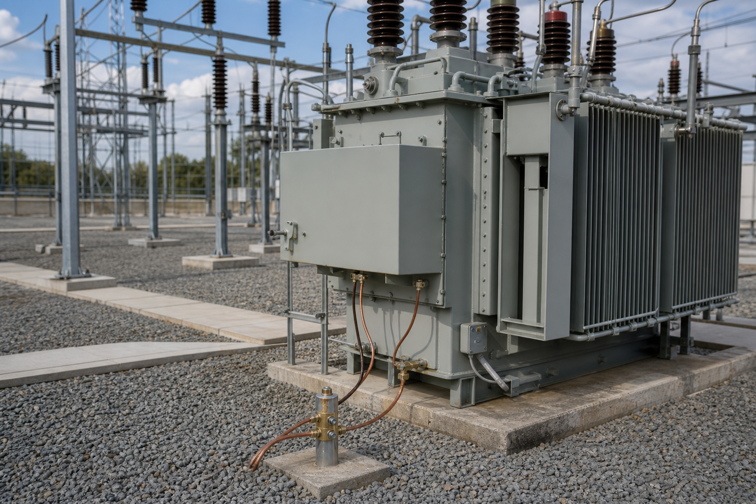
Confirm indoor or outdoor installation, enclosure or tank, cooling, cable entry, access, corrosion, and maintenance. Request the connection diagram, nameplate data, impedance, thermal duty, protection interface, and test documentation. Most grounding transformers at distribution ratings are wound in oil-filled tanks — our oil immersed transformer page lists the tank types, fluids, and protection packages we build — though dry-type grounding units serve indoor and fire-sensitive installations where the study permits.
Standards context
The transformer itself is designed and tested under the IEC 60076 series or the IEEE C57 family, with the zero-sequence impedance and short-time duty as project-specified values verified in test. System earthing practice — fault-current limits, earthing methods, and safety — belongs to system-level standards and studies: IEEE Std 80 governs substation earthing design in IEEE practice, and installation codes (IEC 61936 contexts, or NEC earthing rules in North America) apply at the installation. The neutral grounding resistor carries its own standard family (IEEE C32 class heritage for line-neutral resistors in ANSI practice; IEC market equivalents specified per project). The deliverable set that matters at acceptance: connection diagram, zero-sequence impedance test value, short-time thermal rating, and the interface documentation tying relay settings to the grounding study.
Frequently asked questions
Does a grounding transformer carry load?
Normally no — beyond a small continuous neutral current, it exists for earth-fault duty. The exception is the wye-delta arrangement with an auxiliary secondary serving local load.
Why not just earth one system corner directly?
Because uncontrolled earth-fault current and transient overvoltages follow. The grounding transformer plus resistor lets the study choose the fault current: high enough for protection to see, low enough to limit damage and touch voltages.
What happens if the grounding transformer fails out of service?
The system reverts to ungrounded operation: faults become hard to detect, and transient overvoltages stress insulation — which is why monitoring of the neutral path and a defined response for its loss belong in the protection scheme.
Can I add a grounding transformer to an existing delta system without a study?
No — the fault-current value touches resistor sizing, transformer rating, relay settings, and earthing safety; it is a system redesign done once, with a study, correctly.
How is the neutral current monitored?
A current transformer on the neutral path feeding an overcurrent or earth-fault element, plus temperature devices on the transformer — the alarm logic should come from the same study that set the fault current. The follow-up question to close with your engineer: what trips and what only alarms on sustained neutral current, because that split decides whether a developing fault stops the line or merely announces itself.
Zigzag or wye-delta for a wind collector system?
Zigzag units dominate — pure grounding duty, compact, no secondary to protect — but where station service is wanted at the same node, the wye-delta earns its place.
Procurement scenarios
For a wind-farm or industrial delta network specifying grounding for the first time, order the transformer and NGR from one engineering source with the coordination study delivered as part of the package — split sourcing of transformer and resistor is the classic origin of mismatched time-current duty discovered during commissioning tests. For a retrofit into an operating substation, plan the outage window around zero-sequence impedance verification on site, and order with the interface documentation (CT and relay terminal schedule) agreed with the switchgear supplier in advance. For export projects, confirm the destination market’s earthing conventions and resistor standard expectations at order stage; earthing practice varies enough between IEEE and IEC traditions that late re-documentation costs weeks precisely when energization is being scheduled.
ElectricalCabinet.net can use these inputs to route a grounding-transformer or substation enquiry to the appropriate transformer, switchgear, and protection scope — see our oil immersed transformer platform for the tank and fluid options.
 EN
EN