










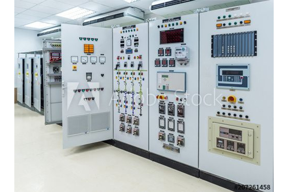
Komponenten für elektrische Schalttafeln werden in jedem Gerät in allen Branchen eingesetzt. Es ist schwierig, alle möglichen Kombinationen zu beschreiben, da jede Branche und die meisten Unternehmen ihre bevorzugten Komponentenspezifikationen festgelegt haben.
Eine Steuertafel ist ein Kasten, der elektrische Komponenten enthält, die für den Betrieb einer Maschine oder eines Prozesses in einer Fabrik erforderlich sind. Eine typische Liste der Komponenten einer industriellen Schalttafel umfasst:
Hauptstromkreisunterbrecher

Sie dient als Verbindungsstelle zwischen der eingehenden Stromleitung und der elektrischen Schalttafel. Ein mechanisches Gerät, das es dem Bediener ermöglicht, die elektrische Verbindung zwischen der Schalttafel oder dem Stromversorgungssystem und der Stromleitung herzustellen oder zu trennen. Die Verwendung oder Umsetzung des primären Leistungsschalters hängt vom jeweiligen Typ des verwendeten Leistungsschalters ab. Seine Hauptfunktion besteht jedoch häufig darin, das Schaltschranksystem zu schützen, indem er das System sofort unterbricht, um es vor Fehlerströmen in der Stromleitung zu schützen. Die Stromleitung, die an den Hauptschalter angeschlossen ist, kann eine Spannung haben, die je nach den spezifischen Lastanforderungen variiert.
Überspannungsableiter

Abzweigleitungsschutzschalter
Er dient als Vermittler zwischen einem Einspeiseleistungsschalter und einem Abzweigstromkreis. Ein mechanisches Gerät, das es einem Bediener ermöglicht, die elektrische Verbindung zwischen der Stromquelle und den elektrischen Geräten herzustellen oder zu trennen. Die Verwendung oder Umsetzung eines Abzweigschutzschalters hängt von der Art des verwendeten Schutzschalters ab, obwohl er häufig als Zwischenmaßnahme zum Schutz elektrischer Geräte vor Netzfehlern dient, indem er den Stromkreis automatisch unterbricht. Bestimmte Ausführungen können auch einen Schutz gegen thermische Erwärmung bieten, nämlich dann, wenn ein hoher Strom durch die Drähte fließt, wenn auch nicht in dem Maße wie bei einem Kurzschluss.
Transformator oder Netzgerät
Die elektrische Schalttafel ist mit Abspanntransformatoren ausgestattet, die die Spannung des Stromnetzes auf die für die elektrische Komponente erforderliche Spannung reduzieren. In Situationen, in denen das Verteilernetz von 575 V bis 120 V reicht und die gewünschte elektrische Spannung noch niedriger ist, wie z. B. 24 V, werden Abspanntransformatoren oder Gleichstromversorgungen verwendet, um die Spannung auf das für die elektrische Schalttafel geeignete Niveau zu reduzieren. Dadurch wird der sichere Betrieb des Systems gewährleistet und die bestimmungsgemäße Funktion der Steuergeräte ermöglicht.

Sobald die elektrische Schalttafel Strom vom Hauptschalter erhält und diesen über einen Transformator oder eine Stromversorgung verteilt, können die verschiedenen Spannungen an Klemmenleisten angeschlossen werden, um die weitere Stromführung innerhalb der Schalttafel zu erleichtern.
Gelegentlich benötigen bestimmte elektrische Geräte mehrere Spannungsebenen. In solchen Fällen ist die Installation mehrerer Abspanntransformatoren oder Gleichstromversorgungen erforderlich, um die vorgesehenen elektrischen Geräte mit einer genauen Spannung zu versorgen.
Klemmleiste

Reihenklemmen sind wichtige elektrische Komponenten, die in hochleistungsfähigen elektrischen Schalttafeln zu finden sind. Sie dienen dem Anschluss zahlreicher Stromquellen oder Spannungsebenen. Die Reihenklemmen verfügen über eine eigene Stromversorgung mit einer bestimmten Spannung, die dann an die entsprechenden Geräte in der Schalttafel verteilt wird.
Speicherprogrammierbare Steuerung (PLC)
Eine speicherprogrammierbare Steuerung (SPS) ist ein Gerät, das programmiert werden kann, um verschiedene industrielle Prozesse zu steuern und zu automatisieren.

Eine speicherprogrammierbare Steuerung (SPS) dient als zentrale Verarbeitungseinheit einer elektrischen Schalttafel, die auf der Grundlage logischer Eingaben arbeitet. Die SPS verfügt über vorgegebene Eingänge, die sie zur Steuerung des gesamten elektrischen Systems von Unternehmen verwendet. Das Gerät ist mit vielen Eingängen von verschiedenen Klemmenblöcken verbunden und erzeugt mehrere Ausgänge auf der Grundlage von Leistungssignalen. An den Fließbändern in der Industrie werden verschiedene Arten von Messgeräten wie Näherungsschalter und Sensoren eingesetzt. Diese Geräte liefern wichtige Eingaben für die speicherprogrammierbare Steuerung (SPS) und ermöglichen ihr, die logische Ausgabe anzupassen und die Systemeffizienz innerhalb der vorgegebenen Parameter zu halten.
Relais und Schütze
Relais sind Schutzeinrichtungen, die die Verbindung zwischen elektrischen Geräten und dem Stromnetz herstellen und unterbrechen. Der Betreiber hat die Kontrolle über die Aktivierung und Deaktivierung von Stromkreisen und kann so den Stromfluss herstellen und unterbrechen. In elektrischen Schalttafeln gibt es drei verschiedene Arten von Relais.

Zum einen gibt es kleine Relais, die die Stromversorgung kompakter elektrischer Geräte wie Leuchten und Ventilatoren regeln. Die zweite Art sind Schütze, d.h. überdimensionierte Relais, die den Betrieb von Motoren regeln. Die dritte Kategorie wird als Hauptsteuerrelais (MCR) bezeichnet und wird für den Notauskreis verwendet. Sie sind für die Unterbrechung der Stromzufuhr zu den Ausgangsgeräten zuständig, wenn der Benutzer eine Notvorrichtung aktiviert.
Netzwerk-Switch

Der Netzwerkschalter steuert die 24-V-Kommunikationsverbindung, die die SPS mit allen anderen Geräten verbindet, die der vorgegebenen Logik und den vom Betreiber definierten Kriterien entsprechen müssen. Der Netzwerkschalter regelt die Verbindung zwischen der SPS und anderen elektrischen Geräten innerhalb der Schalttafel und ermöglicht die Kommunikation.
Die Mensch-Maschine-Schnittstelle (HMI)
Die elektrische Schalttafel weist eine komplizierte interne Konfiguration auf, die aus mehreren elektrischen Komponenten besteht, was den Benutzer vor die Herausforderung stellt, den aktuellen Status zu verstehen, angemessene Entscheidungen zu treffen und dem System Eingaben zu machen.

Die Mensch-Maschine-Schnittstelle (HMI) bietet eine Plattform für den Bediener, um die logischen Prozesse der speicherprogrammierbaren Steuerung (SPS) und der elektrischen Schalttafel zu verstehen. Sie vereinfacht den Prozess der direkten Eingabe. Das Hauptziel der HMI besteht darin, den Bediener bei der Verwaltung der Aufgaben der elektrischen Schalttafel zu unterstützen und ihm die Kontrolle über das Stromversorgungssystem zu ermöglichen.
Druckknöpfe oder Kontrollleuchten
Steuerschalter oder Kontrollleuchten, die durch Drücken aktiviert werden.
Drucktasten sind ein wesentliches elektrisches Element einer elektrischen Schalttafel. Sie befinden sich in der Regel an der Tür der Schalttafel. Typischerweise gibt es einen roten pilzförmigen Druckknopf für Not-Aus und einen Druckknopf zum Zurücksetzen des Maschinensteuerrelais (MCR). Der Bediener verwendet weitere Tasten, um verschiedene Funktionen der Maschine oder des Prozesses zu steuern.
Kontrollleuchten haben eine verblüffende Ähnlichkeit mit Drucktasten, obwohl sie nur als optisches Signal für den Bediener dienen und Informationen über die Aktivitäten des Steuersystems vermitteln.
Gelegentlich sind Drucktaster und Kontrollleuchten in einem einzigen Gerät integriert und werden für mehrere Funktionen eingesetzt.
Schlussfolgerung
Heute haben wir über die Komponenten einer Schalttafel gesprochen. Jede Schalttafel verfügt über eine Hauptstromquelle, die über die gesamte Schalttafel an verschiedene Geräte zur Steuerung und Überwachung verteilt wird.
Elektronische Schalttafeln gibt es in verschiedenen Größen, aber sie haben alle ähnliche Vorrichtungen, über die wir heute gesprochen haben.
Lesen Sie mehr: Wie man effiziente elektrische Schalttafeln entwirft: Eine Schritt-für-Schritt-Anleitung
Updated Selection Guidance
This section is a supplemental review draft. Consolidate overlapping passages before replacing the production URL.
Industrial control panel components should be selected as a system. A panel may contain power-distribution devices, motor-control equipment, PLC and interface hardware, terminals, protection, and enclosure-related parts. The correct list depends on the equipment being controlled, the available supply, the signals exchanged with the process, and the project documentation.
This guide is an update-oriented reference for preparing a specification. It does not assign a universal component list to every panel and does not replace the approved engineering design.
1. Incoming power and isolation
Start by defining how power enters the panel and how it will be isolated for the intended operating and maintenance workflow. The specification may need to identify the incoming disconnecting device, branch protection, control-power source, and any distribution sections. Voltage, current, fault information, and local requirements must come from the project inputs or the selected product documentation.
Do not infer a rating from the enclosure size or from the phrase “industrial control panel.” The incoming arrangement should be checked against the load schedule and the approved design.
2. Motor-control and load devices
The controlled equipment determines whether the panel needs contactors, starters, overload protection, soft starters, variable-frequency drives, relays, or another arrangement. Motor data, starting method, duty cycle, feedback, and process sequence should be collected before the device list is finalized.
For variable-speed applications, the VFD Control Panel Design und VFD Control Panel Components articles provide a focused checklist. They should be read together with the actual motor and process information.
3. PLC, relays, and control interfaces
The control layer may include a PLC, remote I/O, interposing relays, safety-related interfaces, an HMI, or a combination of these. Define what each device is responsible for before assigning terminals:
– PLC or controller: executes the approved control logic; – HMI or operator interface: presents status, commands, and alarms; – relays and interfaces: isolate or adapt signals where the design requires it; – communication hardware: exchanges data with other equipment when specified; and – power supplies: provide the required control voltage for the selected devices.
The PLC-Schaltschrank page is a product-level reference. The actual PLC family, I/O count, protocol, and network arrangement must be defined by the project.
4. Field terminals and signal handling
Terminal blocks create the documented boundary between the panel and field wiring. The I/O list should identify each field signal, normal state, destination, and cable reference. Analog, discrete, communication, and spare points should be distinguishable in the schedule.
Signal conditioning, fuses, surge protection, isolators, or other interface devices may be required depending on the field devices and installation. Do not add them merely because they appear in a generic control-panel diagram.
5. Protection and monitoring
Protection devices and monitoring components should be tied to the equipment and the approved design. Depending on the application, the panel may need branch protection, overload monitoring, phase or voltage monitoring, drive status, process alarms, or fault indication. The component list should state which condition each device detects and what the control system does with that information.
Avoid presenting a component list as proof of compliance with UL, IEC, NFPA, NEMA, or another standard. Compliance and certification depend on the complete assembly, the applicable edition, and the exact product and construction details.
6. Enclosure and thermal-management items
The enclosure, mounting method, cable entries, gland plates, ventilation, fans, filters, heaters, and other thermal or environmental parts are selected from the installation conditions. Record indoor or outdoor location, ambient conditions, moisture or condensation concerns, service access, and required material or finish.
The Elektrische Schaltschränke product area can help route a product inquiry, but a product image alone does not prove a NEMA or IP rating. Confirm the exact model documentation before publishing a rating claim.
7. Documentation that should accompany the component list
The component list is more useful when it connects to a repeatable document set:
| Document | What it confirms |
|---|---|
| Load schedule | Controlled loads and basic electrical data |
| I/O list | Field signals, states, and destinations |
| Bill of materials | Selected devices and quantities |
| Panel layout | Physical positions and access assumptions |
| Terminal schedule | Field cable and terminal references |
| Schematic or functional diagram | Approved circuit relationships |
| Data sheets and manuals | Product-specific limits and interfaces |
Keep the revision of each document aligned. A component change that is not reflected in the I/O list, layout, or terminal schedule can make the panel difficult to build or maintain.
Specification checklist
Before requesting a quotation, provide:
- equipment and load schedule;
- incoming power and control-voltage information;
- control sequence and alarm requirements;
- I/O and communication list;
- installation environment and enclosure constraints;
- preferred device families, if any;
- required drawings, manuals, and inspection documents; and
- known assumptions, exclusions, and future expansion points.
The supplier can then identify the proposed components, assumptions, and exclusions. That creates a clearer comparison than asking for a generic “complete control panel” without process and equipment context.
Wire Duct, DIN Rail, and the Physical Build
Not every component in an electrical control panel carries current — two of the most consequential items are structural. The DIN rail is the standardized metal strip that PLCs, breakers, terminal blocks, relays, and motor controllers clip onto, which is what lets a panel be assembled, wired, and later reconfigured on a bench instead of fabricated in place. Wire duct (wiring raceway) routes and protects the wiring between those devices, keeps power and signal separated, and decides whether a maintenance technician can actually trace a wire five years after commissioning. Duct comes in slotted and unslotted profiles: narrow slots for small-diameter wire, wide slots for thicker bundles, and unslotted or solid-wall duct where protection matters more than tap-in access.
Control Panel Components Summary Table
The individual component sections above explain each device in depth; this table is the one-glance version for planning a panel layout or walking a shop floor:
| Component | Role | Typical power or signal level | Where it sits |
|---|---|---|---|
| Main circuit breaker | Isolate and protect the whole panel | Commonly 120–480 V incoming service | Top of the enclosure, where power enters |
| Branch circuit breakers | Protect each feeder and load circuit | System voltage | Grouped near the main |
| Fuses and surge protection | One-time overcurrent protection; voltage-surge diversion | System voltage | Distribution area |
| Power supply | Convert AC to regulated 24 V DC control power | 480/120 V AC in, 24 V DC out | DIN rail, upper control area |
| Control transformer | Step down AC voltage for control circuits | e.g. 480 V to 120 V AC | Mounted or DIN rail |
| Power distribution blocks | Split large feeders into smaller branch wiring | AC and DC sections | Between supply and devices |
| PLC | Execute the control logic | 24 V DC typically | DIN rail, separated control zone |
| Relays and contactors | Switch loads under PLC command | Coil 24 V DC/120 V AC; contacts up to motor voltage | DIN rail near loads |
| VFDs and soft starters | Motor speed control and ramped starting | Motor voltage class | Lower section, heat and clearance managed |
| Terminal blocks | Terminate field wiring | All levels, segregated | Rows along the duct boundaries |
| Network switch | Link PLC, HMI, and SCADA over Ethernet | 24 V DC, Cat 5/6 cabling | Separated from power wiring |
| HMI | Operator interface and diagnostics display | 24 V DC | Door mounted |
| Push buttons and pilot lights | Hardwired commands and status | Control voltage | Door mounted |
Standards That Govern Control Panel Components
Component selection happens inside a framework of panel-level standards. In North America, UL 508A is the standard for industrial control panels and NFPA 79 covers the electrical side of industrial machinery; in IEC markets the corresponding assembly framework is the IEC 61439 series. Two cautions follow from how these standards work. First, a list of components is not proof of compliance: certification depends on the complete assembly, the applicable edition, and the exact product and construction details. Second, substitutions matter — swapping a breaker or relay family after a panel is designed can void spacing, short-circuit rating, and temperature-rise assumptions that the approval was based on. Treat the component list and the standard it was assessed under as one document, not two.
Control Panel Components FAQ
What are the most important components in a control panel?
The set that appears in nearly every industrial panel is the main breaker, power supply, PLC, relays and contactors, terminal blocks, and an HMI. Everything else — drives, soft starters, network gear — joins that core when the driven equipment and the process call for it.
How does an electrical control panel work?
Power enters through the main breaker and is divided to branch circuits; the power supply derives a safe 24 V DC rail for the control devices. The PLC reads inputs from field devices, makes decisions per its program, and switches outputs through relays and contactors, while the HMI gives the operator visibility and control over the sequence.
Why is 24 V DC so common in control panels?
Because it is low enough to be safe to touch and to wire densely, high enough to drive relays, valves, and sensors reliably over panel-scale distances, and it lets the control world standardize on one supply level regardless of whether the plant incoming supply is 240, 480, or 600 V AC.
What is the difference between a relay and a contactor?
A relay switches small control-level loads like lights, fans, and solenoid coils; a contactor is built for load-level current — motors and heaters — and is used together with an overload device to protect the motor it starts. They share the principle of a coil-operated switch and differ in what they are rated to interrupt.
Browse this topic: Control Panels technical hub
 DE
DE  EN
EN  EN_ZA
EN_ZA  AR
AR  EN_GB
EN_GB  ES
ES  FR
FR  IT
IT  JA
JA  ZH
ZH  TR
TR  RU
RU  EN_CA
EN_CA  EN_AU
EN_AU  NL
NL  PT
PT  FA
FA