










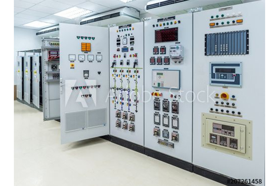
電気制御盤の部品は、あらゆる業界のあらゆる機器に使用されています。各業界と大半の企業が好みの部品仕様を確立しているため、潜在的な組み合わせをすべて定義することは困難です。
制御盤とは、工場の機械や工程を動かすために必要な電気部品が入った箱のことです。典型的な産業用制御盤の部品リストには、以下のものが含まれます:
メイン・サーキット・ブレーカー

入ってくる電力線と電気制御盤との間の接合部として機能する。オペレータが制御盤または電力系統と電力線との間の電気接続を確立または切断できるようにする機械装置。プライマリ・サーキット・ブレーカの使用または実装は、使用するサーキット・ブレーカの特定のタイプに依存する。しかし、その主な機能は、多くの場合、電力線故障電流からシステムを保護するためにシステムを瞬時に切り離し、電気パネルシステムの中間的な保護装置として機能することである。メインサーキットブレーカに接続する電力線は、特定の負荷要件に基づいて変化する電圧レベルを持っている可能性があります。
サージアレスタ

分岐サーキットブレーカー
フィーダ・サーキット・ブレーカと分岐回路の間の仲介の役割を果たす。オペレータが電源と電気機器との間の電気的接続を確立または切断できるようにする機械装置。分岐サーキットブレーカの使用または実装は、採用されるサーキットブレーカの特定のタイプに依存するが、多くの場合、回路を自動的に遮断することにより、電力線障害から電気機器を保護するための仲介手段として機能する。また、短絡ほどではないが、電線に大電流が流れた場合に、熱に対する保護を提供するものもある。
トランスまたは電源
電気制御盤には、電力線からの電圧を電気部品が必要とする特定の電圧に下げる降圧トランスが装備されている。配電線が575Vから120Vの範囲にあり、必要な電気電圧が24Vなどさらに低い場合には、降圧トランスまたは直流電源を使用して、電圧を電気制御盤に適したレベルまで下げます。これにより、システムの安全な動作が保証され、制御装置が意図したとおりに機能するようになります。

電気制御盤がメイン・サーキット・ブレーカーから電気を受け取り、変圧器または電源装置を通して電気を分配すると、様々な電圧を端子台に接続することができ、盤内での電力経路をさらに容易にすることができる。
時には、特定の電気機器が多くのレベルの電圧を必要とすることがある。このような場合、指定された電気機器に正確な電圧を供給するために、複数の降圧トランスや直流電源装置を設置する必要があります。
端子台

端子台は、頑丈な電気制御盤に不可欠な電気部品です。端子台は、多数の電源または電圧レベルを接続するために使用されます。端子台には定義された電圧の専用電源があり、電気制御盤内の関連機器に分配されます。
プログラマブルロジックコントローラ(PLC)
プログラマブル・ロジック・コントローラ(PLC)は、さまざまな工業プロセスを制御し、自動化するためにプログラムされる装置である。

プログラマブルロジックコントローラ(PLC)は、電気制御盤の中央処理ユニットとして機能し、論理入力に基づいて動作する。PLCには所定の入力が用意されており、これを使用して企業の電気システム全体を制御します。このデバイスは、さまざまな端子台からの多くの入力にリンクされ、電力信号に基づいて複数の出力を生成します。産業界の組立ラインには、近接スイッチやセンサーなど、さまざまな種類の検知装置が配置されている。これらのデバイスは、プログラマブル・ロジック・コントローラ(PLC)に不可欠な入力を提供し、論理出力を調整し、指定されたパラメータ内でシステム効率を維持することを可能にします。
リレーとコンタクタ
リレーは、電気機器と送電線の接続を確立・遮断する保護装置である。オペレータは電気回路の起動と停止を制御することができ、電気の流れを確立したり遮断したりすることができる。電気制御盤には3種類のリレーがあります。

まず、照明やファンなどの小型電気機器への電力供給を調整する小型リレーがある。第 2 の種類はコンタクタで、モーターの動作を調整するために使用される特大リレーです。第3のカテゴリーはマスターコントロールリレー(MCR)と呼ばれ、非常停止回路に使用される。これは、ユーザーが緊急装置を作動させた場合に、出力装置へのすべての電力を遮断する役割を果たします。
ネットワークスイッチ

ネットワークスイッチは、PLCを他のすべての機器と接続する24V通信接続を制御します。この接続は、オペレータによって定義された所定のロジックと基準に準拠する必要があります。ネットワークスイッチは、PLCとパネル内の他の電気機器との間のリンクを調整し、通信を可能にします。
ヒューマン・マシン・インターフェース(HMI)
電気制御盤は、複数の電気部品から構成される複雑な内部構成を備えているため、ユーザーが現在の状態を理解し、適切な判断を下し、システムに入力を提供する上で課題がある。

ヒューマン・マシン・インターフェース(HMI)は、オペレータがプログラマブル・ロジック・コントローラ(PLC)や電気制御盤の論理プロセスを理解するためのプラットフォームを提供します。これにより、直接入力を提供するプロセスが簡素化されます。HMIの主な目的は、オペレータが電気制御盤のタスクを管理し、電力システムを制御できるようにすることです。
押しボタンまたはパイロットランプ
押すことで作動する操作スイッチや表示灯。
押しボタンは、電気制御盤に不可欠な電気的要素である。通常、パネルのドアに設置されている。通常、緊急停止用の赤いキノコ型の押しボタンと、機械制御リレー(MCR)をリセットするための押しボタンがあります。オペレータは、機械やプロセスの様々な機能を調整するために、追加のボタンを使用します。
パイロット・ライトは、押しボタンに酷似しているが、オペレーターの視覚信号としてのみ機能し、制御システムの活動に関する情報を伝える。
時には、押しボタンとパイロットランプがひとつの装置に統合され、多くの機能に採用されることもある。
結論
今日は制御盤の構成要素についてお話しました。各制御盤には主電源があり、制御と監視のために盤内の様々な機器に分配されます。
電子制御盤にはさまざまなサイズがあるが、どれも今日話したような似たような装置を持っている。
続きを読む 効率的な電気制御盤の設計方法:ステップ・バイ・ステップ・ガイド
Updated Selection Guidance
This section is a supplemental review draft. Consolidate overlapping passages before replacing the production URL.
Industrial control panel components should be selected as a system. A panel may contain power-distribution devices, motor-control equipment, PLC and interface hardware, terminals, protection, and enclosure-related parts. The correct list depends on the equipment being controlled, the available supply, the signals exchanged with the process, and the project documentation.
This guide is an update-oriented reference for preparing a specification. It does not assign a universal component list to every panel and does not replace the approved engineering design.
1. Incoming power and isolation
Start by defining how power enters the panel and how it will be isolated for the intended operating and maintenance workflow. The specification may need to identify the incoming disconnecting device, branch protection, control-power source, and any distribution sections. Voltage, current, fault information, and local requirements must come from the project inputs or the selected product documentation.
Do not infer a rating from the enclosure size or from the phrase “industrial control panel.” The incoming arrangement should be checked against the load schedule and the approved design.
2. Motor-control and load devices
The controlled equipment determines whether the panel needs contactors, starters, overload protection, soft starters, variable-frequency drives, relays, or another arrangement. Motor data, starting method, duty cycle, feedback, and process sequence should be collected before the device list is finalized.
For variable-speed applications, the VFD Control Panel Design そして VFD Control Panel Components articles provide a focused checklist. They should be read together with the actual motor and process information.
3. PLC, relays, and control interfaces
The control layer may include a PLC, remote I/O, interposing relays, safety-related interfaces, an HMI, or a combination of these. Define what each device is responsible for before assigning terminals:
– PLC or controller: executes the approved control logic; – HMI or operator interface: presents status, commands, and alarms; – relays and interfaces: isolate or adapt signals where the design requires it; – communication hardware: exchanges data with other equipment when specified; and – power supplies: provide the required control voltage for the selected devices.
The PLC制御盤 page is a product-level reference. The actual PLC family, I/O count, protocol, and network arrangement must be defined by the project.
4. Field terminals and signal handling
Terminal blocks create the documented boundary between the panel and field wiring. The I/O list should identify each field signal, normal state, destination, and cable reference. Analog, discrete, communication, and spare points should be distinguishable in the schedule.
Signal conditioning, fuses, surge protection, isolators, or other interface devices may be required depending on the field devices and installation. Do not add them merely because they appear in a generic control-panel diagram.
5. Protection and monitoring
Protection devices and monitoring components should be tied to the equipment and the approved design. Depending on the application, the panel may need branch protection, overload monitoring, phase or voltage monitoring, drive status, process alarms, or fault indication. The component list should state which condition each device detects and what the control system does with that information.
Avoid presenting a component list as proof of compliance with UL, IEC, NFPA, NEMA, or another standard. Compliance and certification depend on the complete assembly, the applicable edition, and the exact product and construction details.
6. Enclosure and thermal-management items
The enclosure, mounting method, cable entries, gland plates, ventilation, fans, filters, heaters, and other thermal or environmental parts are selected from the installation conditions. Record indoor or outdoor location, ambient conditions, moisture or condensation concerns, service access, and required material or finish.
The 電気エンクロージャー product area can help route a product inquiry, but a product image alone does not prove a NEMA or IP rating. Confirm the exact model documentation before publishing a rating claim.
7. Documentation that should accompany the component list
The component list is more useful when it connects to a repeatable document set:
| Document | What it confirms |
|---|---|
| Load schedule | Controlled loads and basic electrical data |
| I/O list | Field signals, states, and destinations |
| Bill of materials | Selected devices and quantities |
| Panel layout | Physical positions and access assumptions |
| Terminal schedule | Field cable and terminal references |
| Schematic or functional diagram | Approved circuit relationships |
| Data sheets and manuals | Product-specific limits and interfaces |
Keep the revision of each document aligned. A component change that is not reflected in the I/O list, layout, or terminal schedule can make the panel difficult to build or maintain.
Specification checklist
Before requesting a quotation, provide:
- equipment and load schedule;
- incoming power and control-voltage information;
- control sequence and alarm requirements;
- I/O and communication list;
- installation environment and enclosure constraints;
- preferred device families, if any;
- required drawings, manuals, and inspection documents; and
- known assumptions, exclusions, and future expansion points.
The supplier can then identify the proposed components, assumptions, and exclusions. That creates a clearer comparison than asking for a generic “complete control panel” without process and equipment context.
Wire Duct, DIN Rail, and the Physical Build
Not every component in an electrical control panel carries current — two of the most consequential items are structural. The DIN rail is the standardized metal strip that PLCs, breakers, terminal blocks, relays, and motor controllers clip onto, which is what lets a panel be assembled, wired, and later reconfigured on a bench instead of fabricated in place. Wire duct (wiring raceway) routes and protects the wiring between those devices, keeps power and signal separated, and decides whether a maintenance technician can actually trace a wire five years after commissioning. Duct comes in slotted and unslotted profiles: narrow slots for small-diameter wire, wide slots for thicker bundles, and unslotted or solid-wall duct where protection matters more than tap-in access.
Control Panel Components Summary Table
The individual component sections above explain each device in depth; this table is the one-glance version for planning a panel layout or walking a shop floor:
| Component | Role | Typical power or signal level | Where it sits |
|---|---|---|---|
| Main circuit breaker | Isolate and protect the whole panel | Commonly 120–480 V incoming service | Top of the enclosure, where power enters |
| Branch circuit breakers | Protect each feeder and load circuit | System voltage | Grouped near the main |
| Fuses and surge protection | One-time overcurrent protection; voltage-surge diversion | System voltage | Distribution area |
| Power supply | Convert AC to regulated 24 V DC control power | 480/120 V AC in, 24 V DC out | DIN rail, upper control area |
| Control transformer | Step down AC voltage for control circuits | e.g. 480 V to 120 V AC | Mounted or DIN rail |
| Power distribution blocks | Split large feeders into smaller branch wiring | AC and DC sections | Between supply and devices |
| PLC | Execute the control logic | 24 V DC typically | DIN rail, separated control zone |
| Relays and contactors | Switch loads under PLC command | Coil 24 V DC/120 V AC; contacts up to motor voltage | DIN rail near loads |
| VFDs and soft starters | Motor speed control and ramped starting | Motor voltage class | Lower section, heat and clearance managed |
| Terminal blocks | Terminate field wiring | All levels, segregated | Rows along the duct boundaries |
| Network switch | Link PLC, HMI, and SCADA over Ethernet | 24 V DC, Cat 5/6 cabling | Separated from power wiring |
| HMI | Operator interface and diagnostics display | 24 V DC | Door mounted |
| Push buttons and pilot lights | Hardwired commands and status | Control voltage | Door mounted |
Standards That Govern Control Panel Components
Component selection happens inside a framework of panel-level standards. In North America, UL 508A is the standard for industrial control panels and NFPA 79 covers the electrical side of industrial machinery; in IEC markets the corresponding assembly framework is the IEC 61439 series. Two cautions follow from how these standards work. First, a list of components is not proof of compliance: certification depends on the complete assembly, the applicable edition, and the exact product and construction details. Second, substitutions matter — swapping a breaker or relay family after a panel is designed can void spacing, short-circuit rating, and temperature-rise assumptions that the approval was based on. Treat the component list and the standard it was assessed under as one document, not two.
Control Panel Components FAQ
What are the most important components in a control panel?
The set that appears in nearly every industrial panel is the main breaker, power supply, PLC, relays and contactors, terminal blocks, and an HMI. Everything else — drives, soft starters, network gear — joins that core when the driven equipment and the process call for it.
How does an electrical control panel work?
Power enters through the main breaker and is divided to branch circuits; the power supply derives a safe 24 V DC rail for the control devices. The PLC reads inputs from field devices, makes decisions per its program, and switches outputs through relays and contactors, while the HMI gives the operator visibility and control over the sequence.
Why is 24 V DC so common in control panels?
Because it is low enough to be safe to touch and to wire densely, high enough to drive relays, valves, and sensors reliably over panel-scale distances, and it lets the control world standardize on one supply level regardless of whether the plant incoming supply is 240, 480, or 600 V AC.
What is the difference between a relay and a contactor?
A relay switches small control-level loads like lights, fans, and solenoid coils; a contactor is built for load-level current — motors and heaters — and is used together with an overload device to protect the motor it starts. They share the principle of a coil-operated switch and differ in what they are rated to interrupt.
Browse this topic: Control Panels technical hub
 JA
JA  EN
EN  EN_ZA
EN_ZA  AR
AR  EN_GB
EN_GB  DE
DE  ES
ES  FR
FR  IT
IT  ZH
ZH  TR
TR  RU
RU  EN_CA
EN_CA  EN_AU
EN_AU  NL
NL  PT
PT  FA
FA