










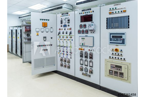
تُستخدم مكونات لوحة التحكم الكهربائية في كل قطعة من المعدات في جميع الصناعات. من الصعب تحديد جميع التوليفات المحتملة نظرًا لأن كل صناعة وغالبية الشركات قد حددت مواصفات المكونات المفضلة لديها.
لوحة التحكم هي صندوق يحتوي على مكونات كهربائية مطلوبة لتشغيل ماكينة أو عملية في المصنع. وتشمل قائمة مكونات لوحة التحكم الصناعية النموذجية ما يلي:
قاطع الدائرة الكهربائية الرئيسية

يعمل كوصلة بين خط الطاقة الوارد ولوحة التحكم الكهربائية. جهاز ميكانيكي يمكّن المشغل من إنشاء أو قطع التوصيل الكهربائي بين لوحة التحكم أو نظام الطاقة وخط الطاقة. ويتوقف استخدام أو تنفيذ قاطع الدارة الرئيسي على النوع المحدد من قواطع الدارة الكهربائية المستخدمة. ومع ذلك، غالبًا ما تكون وظيفته الأساسية هي العمل كوسيلة حماية وسيطة لنظام اللوحة الكهربائية، حيث يقوم بفصل النظام على الفور من أجل حمايته من تيارات أعطال خط الطاقة. قد يكون لخط الطاقة المتصل بقاطع الدارة الكهربائية الرئيسي مستوى جهد يختلف بناءً على متطلبات الحمل المحدد.
مانع زيادة التيار الكهربائي

قاطع الدائرة الفرعية
يعمل كوسيط بين قاطع دائرة التغذية والدائرة الفرعية. جهاز ميكانيكي يمكّن المشغل من إنشاء أو قطع التوصيل الكهربائي بين مصدر الطاقة والأجهزة الكهربائية. ويتوقف استخدام أو تنفيذ قاطع الدارة الفرعية على النوع المحدد من قواطع الدارة الكهربائية المستخدمة، على الرغم من أنه غالباً ما يعمل كإجراء وسيط لحماية المعدات الكهربائية من أعطال خط الطاقة عن طريق قطع الدائرة الكهربائية تلقائياً. قد توفر بعض الإصدارات أيضًا حماية ضد الحرارة الحرارية، أي عندما يتم سحب تيار كبير عبر الأسلاك، وإن لم يكن إلى حد حدوث ماس كهربائي.
المحول أو مزود الطاقة
لوحة التحكم الكهربائية مزودة بمحولات تنحية تقلل الجهد من خط الطاقة إلى الجهد المحدد الذي يحتاجه المكون الكهربائي. في الحالات التي يتراوح فيها خط التوزيع من 575 فولت إلى 120 فولت ويكون الجهد الكهربائي المطلوب أقل، مثل 24 فولت، يتم استخدام محولات تنحي أو إمدادات طاقة تيار مستمر لتقليل الجهد إلى المستوى المناسب للوحة التحكم الكهربائية. وهذا يضمن التشغيل الآمن للنظام ويسمح لأجهزة التحكم بالعمل على النحو المطلوب

بمجرد أن تستقبل لوحة التحكم الكهربائية الكهرباء من قاطع الدارة الرئيسي وتوزعها من خلال محول أو مصدر طاقة، يمكن توصيل الفولتية المختلفة بالكتل الطرفية لتسهيل توجيه المزيد من الطاقة داخل اللوحة.
في بعض الأحيان، تحتاج معدات كهربائية معينة إلى مستويات عديدة من الجهد. وفي مثل هذه الحالات، يكون من الضروري تركيب عدة محولات تنحية أو إمدادات طاقة تيار مستمر لتوفير جهد كهربائي دقيق للمعدات الكهربائية المحددة.
الكتلة الطرفية

الكتل الطرفية هي مكونات كهربائية أساسية موجودة في لوحات التحكم الكهربائية شديدة التحمل. وهي تستخدم لتوصيل العديد من مصادر الطاقة أو مستويات الجهد. تحتوي الكتل الطرفية على مصدر طاقة مخصص بجهد كهربائي محدد، والذي يتم توزيعه بعد ذلك على المعدات ذات الصلة الموجودة في جميع أنحاء لوحة التحكم الكهربائية.
وحدة التحكم المنطقي القابلة للبرمجة (PLC)
وحدة التحكم المنطقية القابلة للبرمجة (PLC) هي جهاز يمكن برمجته للتحكم في العمليات الصناعية المختلفة وأتمتتها.

تعمل وحدة التحكم المنطقي القابلة للبرمجة (PLC) كوحدة المعالجة المركزية للوحة التحكم الكهربائية، وتعمل على أساس المدخلات المنطقية. يتم تزويد جهاز التحكم المنطقي القابل للبرمجة (PLC) بمدخلات محددة مسبقًا، والتي يستخدمها للتحكم في النظام الكهربائي للمؤسسات بالكامل. يرتبط الجهاز بالعديد من المدخلات من كتل طرفية مختلفة وينتج مخرجات متعددة بناءً على إشارات الطاقة. يتم نشر أنواع مختلفة من أجهزة الاستشعار، مثل مفاتيح القرب وأجهزة الاستشعار، على خطوط التجميع في الصناعات. وتوفر هذه الأجهزة مدخلات أساسية لوحدة التحكم المنطقي القابلة للبرمجة (PLC)، مما يمكّنها من ضبط المخرجات المنطقية والحفاظ على كفاءة النظام ضمن معايير محددة.
المرحلات والموصلات
المرحلات هي أجهزة وقائية تنشئ وتقطع الاتصال بين المعدات الكهربائية وخط الطاقة. يُمنح المشغل التحكم في تنشيط وإلغاء تنشيط الدوائر الكهربائية، مما يسمح له بإنشاء وقطع تدفق الكهرباء. تحتوي لوحات التحكم الكهربائية على ثلاثة أنواع متميزة من المرحلات.

أولاً، هناك نوعان من المرحلات الصغيرة التي تنظم إمداد الطاقة للأجهزة الكهربائية المدمجة، مثل المصابيح والمراوح. أما النوع الثاني فيتألف من الموصلات، وهي مرحلات كبيرة الحجم تستخدم لتنظيم تشغيل المحركات. أما الفئة الثالثة فيشار إليها باسم مرحلات التحكم الرئيسية (MCR) وتستخدم لدائرة الإيقاف الطارئ. وهي مسؤولة عن قطع جميع الطاقة عن أجهزة الإخراج في حالة قيام المستخدم بتنشيط جهاز الطوارئ.
مفتاح الشبكة

يتحكم مفتاح الشبكة في وصلة الاتصال بجهد 24 فولت التي تربط وحدة التحكم المنطق المنطقية القابلة للبرمجة (PLC) بجميع المعدات الأخرى، والتي يجب أن تلتزم بالمنطق والمعايير المحددة مسبقًا التي يحددها المشغلون. ينظم مفتاح الشبكة الوصلة بين PLC والمعدات الكهربائية الأخرى داخل اللوحة، مما يتيح الاتصال.
واجهة الآلة البشرية (HMI)
وتتميز لوحة التحكم الكهربائية بتكوين داخلي معقد، يضم العديد من المكونات الكهربائية، وبالتالي تشكل تحديات للمستخدم في فهم الحالة الحالية واتخاذ القرارات المناسبة وتوفير المدخلات للنظام.

توفر الواجهة بين الإنسان والآلة (HMI) منصة للمشغل لفهم العمليات المنطقية لوحدة التحكم المنطقي القابلة للبرمجة (PLC) ولوحة التحكم الكهربائية. وهي تبسط عملية توفير المدخلات المباشرة. الهدف الأساسي من واجهة الواجهة HMI هو مساعدة المشغِّل في إدارة مهام لوحة التحكم الكهربائية وتمكينه من الاحتفاظ بالسيطرة على نظام الطاقة.
أزرار الضغط أو المصابيح الإرشادية
مفاتيح التحكم أو أضواء المؤشرات التي يتم تنشيطها بالضغط عليها.
أزرار الضغط هي عنصر كهربائي أساسي في لوحة التحكم الكهربائية. وعادةً ما تكون موجودة عند باب اللوحة. عادة، يوجد عادةً زر ضغط أحمر على شكل فطر لإيقاف الطوارئ وزر ضغط لإعادة ضبط مرحل التحكم في الماكينة (MCR). يستخدم المشغل أزرارًا إضافية لتنظيم الوظائف المختلفة للماكينة أو العملية.
تتشابه الأضواء الإرشادية بشكل لافت للنظر مع أزرار الضغط، على الرغم من أنها تعمل فقط كإشارة بصرية للمشغل، حيث تنقل المعلومات حول أنشطة نظام التحكم.
في بعض الأحيان، يتم دمج الأزرار الضاغطة والأضواء الإرشادية في جهاز واحد وتوظيفها في العديد من الوظائف.
الخاتمة
تحدثنا اليوم عن مكونات لوحة التحكم. سيكون لكل لوحة تحكم مصدر طاقة رئيسي قادم يتم توزيعه في جميع أنحاء اللوحة على أجهزة مختلفة للتحكم والمراقبة.
ستأتي لوحات التحكم الإلكترونية بأحجام مختلفة ولكن جميعها تحتوي على أجهزة متشابهة تحدثنا عنها اليوم.
اقرأ المزيد: كيفية تصميم لوحات تحكم كهربائية فعالة: دليل خطوة بخطوة
Updated Selection Guidance
This section is a supplemental review draft. Consolidate overlapping passages before replacing the production URL.
Industrial control panel components should be selected as a system. A panel may contain power-distribution devices, motor-control equipment, PLC and interface hardware, terminals, protection, and enclosure-related parts. The correct list depends on the equipment being controlled, the available supply, the signals exchanged with the process, and the project documentation.
This guide is an update-oriented reference for preparing a specification. It does not assign a universal component list to every panel and does not replace the approved engineering design.
1. Incoming power and isolation
Start by defining how power enters the panel and how it will be isolated for the intended operating and maintenance workflow. The specification may need to identify the incoming disconnecting device, branch protection, control-power source, and any distribution sections. Voltage, current, fault information, and local requirements must come from the project inputs or the selected product documentation.
Do not infer a rating from the enclosure size or from the phrase “industrial control panel.” The incoming arrangement should be checked against the load schedule and the approved design.
2. Motor-control and load devices
The controlled equipment determines whether the panel needs contactors, starters, overload protection, soft starters, variable-frequency drives, relays, or another arrangement. Motor data, starting method, duty cycle, feedback, and process sequence should be collected before the device list is finalized.
For variable-speed applications, the VFD Control Panel Design و VFD Control Panel Components articles provide a focused checklist. They should be read together with the actual motor and process information.
3. PLC, relays, and control interfaces
The control layer may include a PLC, remote I/O, interposing relays, safety-related interfaces, an HMI, or a combination of these. Define what each device is responsible for before assigning terminals:
– PLC or controller: executes the approved control logic; – HMI or operator interface: presents status, commands, and alarms; – relays and interfaces: isolate or adapt signals where the design requires it; – communication hardware: exchanges data with other equipment when specified; and – power supplies: provide the required control voltage for the selected devices.
إن خزانة التحكم PLC page is a product-level reference. The actual PLC family, I/O count, protocol, and network arrangement must be defined by the project.
4. Field terminals and signal handling
Terminal blocks create the documented boundary between the panel and field wiring. The I/O list should identify each field signal, normal state, destination, and cable reference. Analog, discrete, communication, and spare points should be distinguishable in the schedule.
Signal conditioning, fuses, surge protection, isolators, or other interface devices may be required depending on the field devices and installation. Do not add them merely because they appear in a generic control-panel diagram.
5. Protection and monitoring
Protection devices and monitoring components should be tied to the equipment and the approved design. Depending on the application, the panel may need branch protection, overload monitoring, phase or voltage monitoring, drive status, process alarms, or fault indication. The component list should state which condition each device detects and what the control system does with that information.
Avoid presenting a component list as proof of compliance with UL, IEC, NFPA, NEMA, or another standard. Compliance and certification depend on the complete assembly, the applicable edition, and the exact product and construction details.
6. Enclosure and thermal-management items
The enclosure, mounting method, cable entries, gland plates, ventilation, fans, filters, heaters, and other thermal or environmental parts are selected from the installation conditions. Record indoor or outdoor location, ambient conditions, moisture or condensation concerns, service access, and required material or finish.
إن العبوات الكهربائية product area can help route a product inquiry, but a product image alone does not prove a NEMA or IP rating. Confirm the exact model documentation before publishing a rating claim.
7. Documentation that should accompany the component list
The component list is more useful when it connects to a repeatable document set:
| Document | What it confirms |
|---|---|
| Load schedule | Controlled loads and basic electrical data |
| I/O list | Field signals, states, and destinations |
| Bill of materials | Selected devices and quantities |
| Panel layout | Physical positions and access assumptions |
| Terminal schedule | Field cable and terminal references |
| Schematic or functional diagram | Approved circuit relationships |
| Data sheets and manuals | Product-specific limits and interfaces |
Keep the revision of each document aligned. A component change that is not reflected in the I/O list, layout, or terminal schedule can make the panel difficult to build or maintain.
Specification checklist
Before requesting a quotation, provide:
- equipment and load schedule;
- incoming power and control-voltage information;
- control sequence and alarm requirements;
- I/O and communication list;
- installation environment and enclosure constraints;
- preferred device families, if any;
- required drawings, manuals, and inspection documents; and
- known assumptions, exclusions, and future expansion points.
The supplier can then identify the proposed components, assumptions, and exclusions. That creates a clearer comparison than asking for a generic “complete control panel” without process and equipment context.
Wire Duct, DIN Rail, and the Physical Build
Not every component in an electrical control panel carries current — two of the most consequential items are structural. The DIN rail is the standardized metal strip that PLCs, breakers, terminal blocks, relays, and motor controllers clip onto, which is what lets a panel be assembled, wired, and later reconfigured on a bench instead of fabricated in place. Wire duct (wiring raceway) routes and protects the wiring between those devices, keeps power and signal separated, and decides whether a maintenance technician can actually trace a wire five years after commissioning. Duct comes in slotted and unslotted profiles: narrow slots for small-diameter wire, wide slots for thicker bundles, and unslotted or solid-wall duct where protection matters more than tap-in access.
Control Panel Components Summary Table
The individual component sections above explain each device in depth; this table is the one-glance version for planning a panel layout or walking a shop floor:
| Component | Role | Typical power or signal level | Where it sits |
|---|---|---|---|
| Main circuit breaker | Isolate and protect the whole panel | Commonly 120–480 V incoming service | Top of the enclosure, where power enters |
| Branch circuit breakers | Protect each feeder and load circuit | System voltage | Grouped near the main |
| Fuses and surge protection | One-time overcurrent protection; voltage-surge diversion | System voltage | Distribution area |
| Power supply | Convert AC to regulated 24 V DC control power | 480/120 V AC in, 24 V DC out | DIN rail, upper control area |
| Control transformer | Step down AC voltage for control circuits | e.g. 480 V to 120 V AC | Mounted or DIN rail |
| Power distribution blocks | Split large feeders into smaller branch wiring | AC and DC sections | Between supply and devices |
| PLC | Execute the control logic | 24 V DC typically | DIN rail, separated control zone |
| Relays and contactors | Switch loads under PLC command | Coil 24 V DC/120 V AC; contacts up to motor voltage | DIN rail near loads |
| VFDs and soft starters | Motor speed control and ramped starting | Motor voltage class | Lower section, heat and clearance managed |
| Terminal blocks | Terminate field wiring | All levels, segregated | Rows along the duct boundaries |
| Network switch | Link PLC, HMI, and SCADA over Ethernet | 24 V DC, Cat 5/6 cabling | Separated from power wiring |
| HMI | Operator interface and diagnostics display | 24 V DC | Door mounted |
| Push buttons and pilot lights | Hardwired commands and status | Control voltage | Door mounted |
Standards That Govern Control Panel Components
Component selection happens inside a framework of panel-level standards. In North America, UL 508A is the standard for industrial control panels and NFPA 79 covers the electrical side of industrial machinery; in IEC markets the corresponding assembly framework is the IEC 61439 series. Two cautions follow from how these standards work. First, a list of components is not proof of compliance: certification depends on the complete assembly, the applicable edition, and the exact product and construction details. Second, substitutions matter — swapping a breaker or relay family after a panel is designed can void spacing, short-circuit rating, and temperature-rise assumptions that the approval was based on. Treat the component list and the standard it was assessed under as one document, not two.
Control Panel Components FAQ
What are the most important components in a control panel?
The set that appears in nearly every industrial panel is the main breaker, power supply, PLC, relays and contactors, terminal blocks, and an HMI. Everything else — drives, soft starters, network gear — joins that core when the driven equipment and the process call for it.
How does an electrical control panel work?
Power enters through the main breaker and is divided to branch circuits; the power supply derives a safe 24 V DC rail for the control devices. The PLC reads inputs from field devices, makes decisions per its program, and switches outputs through relays and contactors, while the HMI gives the operator visibility and control over the sequence.
Why is 24 V DC so common in control panels?
Because it is low enough to be safe to touch and to wire densely, high enough to drive relays, valves, and sensors reliably over panel-scale distances, and it lets the control world standardize on one supply level regardless of whether the plant incoming supply is 240, 480, or 600 V AC.
What is the difference between a relay and a contactor?
A relay switches small control-level loads like lights, fans, and solenoid coils; a contactor is built for load-level current — motors and heaters — and is used together with an overload device to protect the motor it starts. They share the principle of a coil-operated switch and differ in what they are rated to interrupt.
Browse this topic: Control Panels technical hub
 AR
AR  EN
EN  EN_ZA
EN_ZA  EN_GB
EN_GB  DE
DE  ES
ES  FR
FR  IT
IT  JA
JA  ZH
ZH  TR
TR  RU
RU  EN_CA
EN_CA  EN_AU
EN_AU  NL
NL  PT
PT  FA
FA